Toyota RAV4 (XA40) 2013-2018 Service Manual: Headlight relay circuit
Description
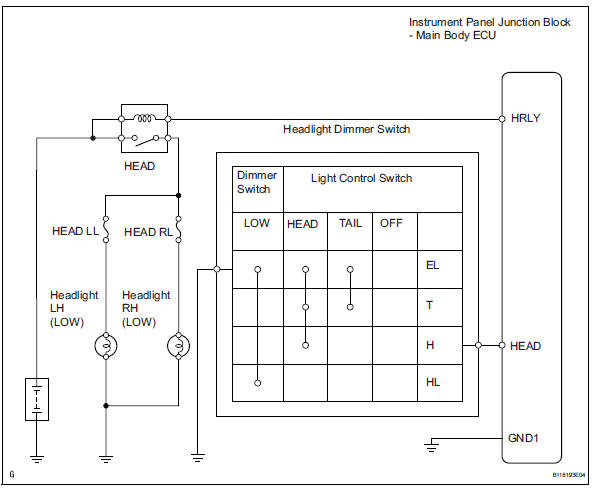
When the light control switch, located on the headlight dimmer switch, is turned to the head position, the head relay illuminates the headlights.
Wiring diagram
Inspection procedure
- Perform active test by intelligent tester (headlight)
- Connect the intelligent tester (with can vim) to the dlc3.
- Turn the ignition switch on and press the intelligent tester main switch on.
- Select the item below in the active test and then check the relay operation.

Ok: headlight comes on

- Inspect fuse (head ll, head rl)
- Remove the head ll fuse and head rl fuse from the engine room no. 2 Relay block.
- Measure the resistance of the fuses.
Standard resistance:
below 1 

- Inspect headlight relay (marking: head)
- Remove the headlight relay from the engine room no. 2 Relay block.
- Measure the resistance of the relay.
Standard resistance 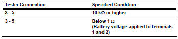

- Inspect bulb (headlight bulb)
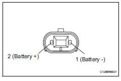
- Remove the headlight bulbs (low).
- Connect the positive (+) lead from the battery to terminal 2 and the negative (-) lead to terminal 1, then check that the bulb illuminates.
Ok: bulb illuminates.

- Check wire harness (main body ecu - battery)
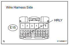
- Disconnect the e15 main body ecu connector.
- Measure the voltage of the wire harness side connector.
Standard voltage 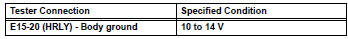

- Check instrument panel junction block (main body ecu)
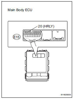
- Measure the voltage of the main body ecu.
Standard voltage 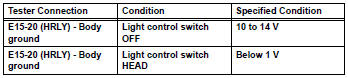

Repair or replace harness and connector (head relay - headlight bulb and body ground)
- Check wire harness (headlight dimmer switch - main body ecu)
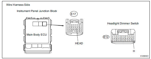
- Disconnect the e17 main body ecu connector.
- Disconnect the e12 headlight dimmer switch connector.
- Measure the resistance of the wire harness side connectors.
Standard resistance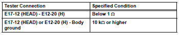

- Inspect headlight dimmer switch
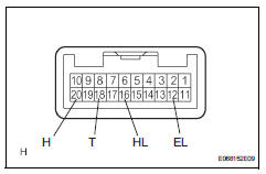
- Disconnect the e12 headlight dimmer switch.
- Measure the resistance of the switch.
Standard resistance 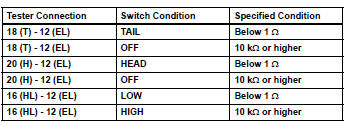

Repair or replace harness and connector (headlight dimmer switch - body ground)
 Stop light switch circuit
Description
When the stop light switch is turned on, current flows to the stop lights to
illuminate them.
Wiring diagram
Inspection procedure
Inspect fuse (stop)
Remove the stop fus ...
 Drl relay circuit
Description
The main body ecu controls the daytime running light no. 2 Relay (marking:
drl no.2).
Wiring diagram
Inspection procedure
Inspect daytime running light relay (marking: drl no. ...
Other materials:
Compressor solenoid circuit (2005/11-2006/01)
Description
In this circuit, the compressor receives a refrigerant compression demand
signal from the air conditioning
amplifier. Based on this signal, the compressor changes the degree of
refrigerant compression.
Wiring diagram
Inspection procedure
Read value of intelligent ...
System description
General
The front passenger occupant classification system
judges whether the front passenger seat is occupied
or not in accordance with the seat belt buckle
status; and whether the seat is occupied by an adult
or child (with child seat) in accordance with the load
that is applied ...
Steering angle sensor zero point malfunction
Description
The skid control ecu learns the steering sensor zero point every time the
ignition switch is turned on and
the vehicle is driven at 35 km/h (22 mph) or more for approximately 5 seconds.
The ecu also stores the
previous zero point.
If front wheel alignment or the steering wh ...
