Toyota RAV4 (XA40) 2013-2018 Service Manual: Stop light switch circuit
Description
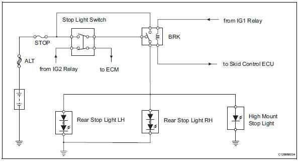
When the stop light switch is turned on, current flows to the stop lights to illuminate them.
Wiring diagram
Inspection procedure
- Inspect fuse (stop)
- Remove the stop fuse from the instrument panel junction block.
- Measure the resistance of the fuse.
Standard resistance:
below 1 

- Inspect stop light (rear combination light)
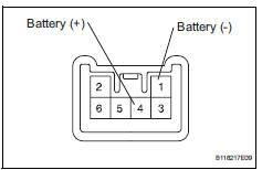
- Remove the rear combination light.
- Connect the positive (+) lead from the battery to terminal 4 and the negative (-) lead to terminal 1, then check that the light comes on.
Ok: light comes on.


- Inspect rear stop light (high mount stop light)
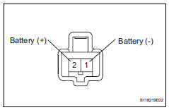
- Remove the high mount stop light assembly.
- Connect the positive (+) lead from the battery to terminal 2 and the negative (-) lead to terminal 1, then check that the light comes on.
Ok: light comes on

- Inspect brk relay
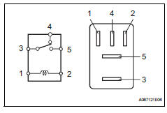
- Remove the brk relay from the engine room no. 1 Relay block.
- Measure the resistance of the relay.
Standard resistance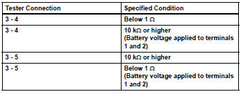

- Inspect stop light switch
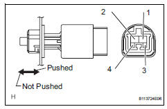
- Remove the stop light switch.
- Measure the resistance of the switch.
Standard resistance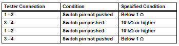

- Check wire harness (stop light switch - battery)
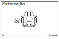
- Disconnect the a3 stop light switch connector.
- Measure the voltage of the wire harness side connector.
Standard voltage 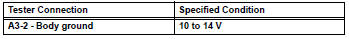

- Check wire harness (stop light switch - rear stop light)
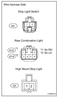
- Disconnect the a3 stop light switch connector.
- Disconnect the k12 and k14 rear combination light connectors.
- Disconnect the q1 high mount stop light connector.
- Measure the resistance of the wire harness side connectors.
Standard resistance 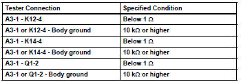

Repair or replace harness and connector (rear stop light - body ground)
 Data list / active test
Read data list
Hint:
Using the intelligent tester's data list allows switch,
sensor, actuator and other item values to be read without
removing any parts. Reading the data list early in
...
 Headlight relay circuit
Description
When the light control switch, located on the headlight dimmer switch, is
turned to the head position, the
head relay illuminates the headlights.
Wiring diagram
Inspection proced ...
Other materials:
Pressure sensor circuit
Description
This dtc is output when the refrigerant pressure is either extremely low
(0.19 Mpa [2.0 Kgf/cm2, 28 psi]
or less) or extremely high (3.14 Mpa [32.0 Kgf/cm2, 455 psi] or more). The air
conditioning pressure
sensor, which is installed on the pipe of the high pressure side, detec ...
Bus ic communication malfunction
Description
The air conditioning harness connects the air conditioning amplifier and the
servos. The air conditioning
amplifier supplies power and sends operation instructions to each servo through
the air conditioning
harness. Each servo sends damper position information to the air condi ...
Removal
Disconnect cable from negative battery
terminal
Caution:
Wait at least 90 seconds after disconnecting the
cable from the negative (-) battery terminal to
prevent airbag and seat belt pretensioner activation.
Remove no. 1 Engine cover (see page es-410)
Remove camshaft timing oil cont ...
