Toyota RAV4 (XA40) 2013-2018 Service Manual: Propeller shaft assembly
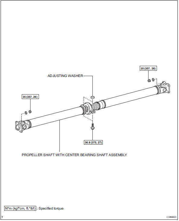
Components
Removal
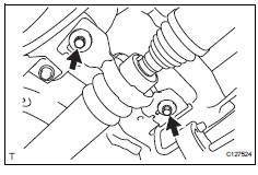
- Remove propeller shaft with center bearing shaft assembly
- Remove the 2 bolts and 2 adjusting washers, and disconnect the propeller with center bearing shaft.
Notice:
- During the removal, do not exert excessive force on the universal joint.
- When removing, transporting or storing the propeller with center bearing shaft assembly, do not allow the no. 2 Joint angle to exceed 20Đ®
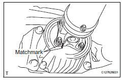
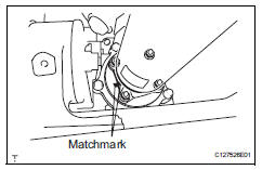
- Place matchmarks on the differential carrier and propeller shaft.
- Remove the 4 nuts and 4 washers, and disconnect the propeller shaft and differential carrier.
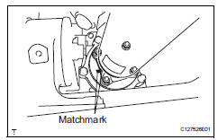
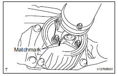
- Place matchmarks on the transfer and propeller shaft.
- Remove the 4 nuts and 4 washers, and disconnect the propeller shaft from the transfer.
Inspection
- Inspect propeller shaft with center bearing shaft assembly
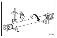
- Using a dial indicator, measure the propeller shaft runout for front side.
Maximum runout: 0.4 Mm (0.02 In.)
If the shaft runout is greater than the maximum, replace the propeller shaft.
Notice:
Place the dial indicator on the center of the shaft, and perpendicular to the shaft.
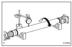
- Using a dial indicator, measure the propeller shaft runout for rear side.
Maximum runout: 0.4 Mm (0.02 In.)
If the shaft runout is greater than the maximum, replace the propeller shaft.
Notice:
Place the dial indicator on the center of the shaft, and perpendicular to the shaft.
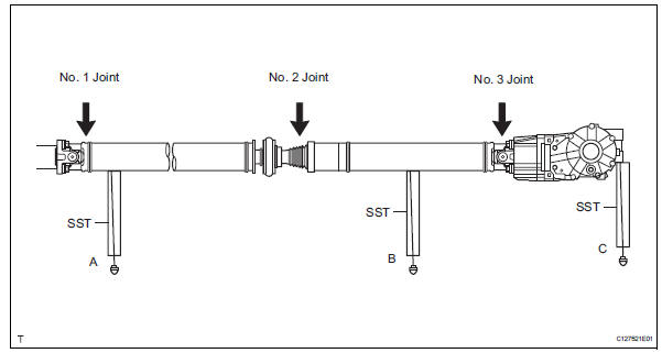
- Inspect joint angle
- Before the angle measurement, use procedures like the examples below to stabilize each part.
- Rotate the propeller shaft several times by hand.
- Set the jack to the differential, and raise and lower it.
Notice:
Perform the measurement with a 4 post lift or pit so that the vehicle condition is as close to a standard ground condition as possible.
- Using sst, measure the installation angle of the propeller shaft for front side (a in illustration).
Sst 09370-50010 standard angle a:
-2Đ´9'
-3Đ°1' For w/ 3rd seat
- Using sst, measure the installation angle of the propeller shaft for front side (a in illustration) and propeller shaft for rear side (b in illustration).
Sst 09370-50010
Standard angle a-b: 1Đł5'
- Using sst, measure the installation angle of the propeller shaft for rear side (b in illustration) and differential carrier rear side (c in illustration).
Sst 09370-50010
Standard angle b-c: 2Đ°4'
- If the result is not as specified, replace the center support bearing adjusting washer with a more appropriate one.
Notice:
- Use washers of the same thickness on the left and right sides.
- Do not use 2 or more washers stacked together
Standard adjusting washer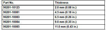
Installation
- Temporarily install propeller shaft with center bearing shaft assembly
- Align the matchmarks of the transfer and propeller shaft.
- Temporarily install the propeller shaft with center bearing with the 4 nuts and 4 washers.
- Align the matchmarks of the differential carrier and propeller shaft.
- Temporarily install the propeller shaft with center bearing with the 4 bolts and 4 washers.
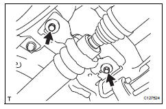
- Temporarily install the center support bearing and center support bearing washer with the 2 bolts.
- Tighten propeller shaft with center bearing shaft assembly
- Tighten the 4 nuts of the propeller shaft and transfer
to the torque specification.
Torque: 35 n*m (357 kgf*cm, 26 ft.*Lbf)
- Tighten the 4 nuts of the propeller shaft and
differential carrier to the torque specification.
Torque: 35 n*m (357 kgf*cm, 26 ft.*Lbf)
- Check that the center line of the center support bearing housing is perpendicular to the axis of the propeller shaft.
- Tighten the 2 bolts of the center support bearing to
the torque specification.
Torque: 36.8 N*m (375 kgf*cm, 27 ft.*Lbf)
- Inspect joint angle (see page pr-4)
 Propeller shaft system
Problem symptoms table
Hint:
Use the table below to help determine the cause of the
problem symptom. The potential causes of the symptoms are
listed in order of probability in the "suspected ...
 Seat
Seat
...
Other materials:
Test mode procedure
Test mode check
Hint:
When entering the test mode, the tire pressure
warning ecu sets all the test dtcs first. After
completing the test mode for each inspection item, the
dtcs that are determined normal by the tire pressure
warning ecu will be erased.
The dtcs for other inspec ...
Map light assembly
Components
Removal
Disconnect cable from negative battery
terminal
Caution:
Wait at least 90 seconds after disconnecting the
cable from the negative (-) battery terminal to
prevent airbag and seat belt pretensioner activation.
Remove map light assembly
Detach the 4 cli ...
Initializing the tire pressure
warning system (if
equipped)
â– The tire pressure warning
system must be initialized
in the following circumstances:
When rotating the tires.
When changing the tire.
After registering the ID codes.
When the tire pressure warning
system is initialized, the current
tire inflation pressure is set as
the benchmark pressure.
â ...
