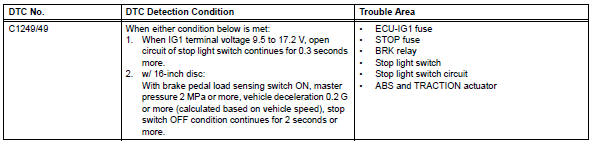
Toyota RAV4 (XA40) 2013-2018 Service Manual: Open in stop light switch circuit
Description
The skid control ecu detects the brake operating conditions through a signal transmitted by the stop light switch. The skid control ecu incorporates an open circuit detection circuit. This dtc is set under either of the following conditions:
- An open is detected in the stop light signal input line when the stop light switch is off.
- An open is detected in the stop light circuit lead to the ground when the stop light switch is off.
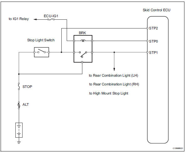
Wiring diagram
Inspection procedure
- Read value of intelligent tester (stop light switch)
- Check the data list for proper functioning of the stop light switch.
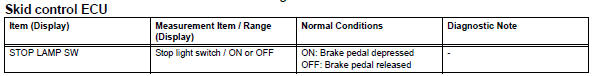
Ok: on (brake pedal is depressed) appears on the screen.


- Check wire harness (stp voltage)
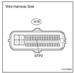
- Disconnect the a19 ecu connector.
- Measure the voltage of the wire harness side connector.
Standard voltage 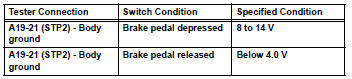


Replace abs and traction actuator assembly
- Inspect fuse (stop, ecu-ig1)
- Remove the stop fuse and ecu-ig1 fuse from the instrument panel junction block.
- Measure the resistance of the fuse.
Standard resistance:
below 1 


- Inspect stop light control relay (marking: brk)
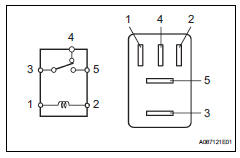
- Remove the stop light control relay from the engine room no. 1 Relay block.
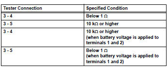
- Measure the resistance of the relay.


- Inspect stop light switch assembly
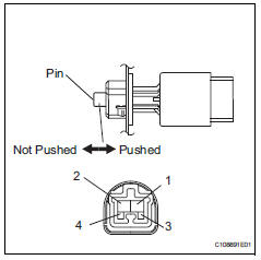
- Disconnect the stop light switch connector.
- Measure the resistance of the switch.
Standard resistance 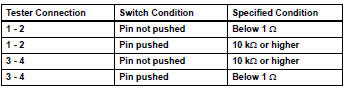


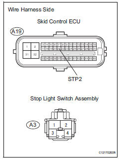
- Check wire harness (skid control ecu - stop light switch)
- Disconnect the a19 ecu connector.
- Disconnect the a3 switch connector.
- Measure the resistance of the wire harness side connectors.
- Disconnect the a19 ecu connector.
- Disconnect the a3 switch connector.
- Measure the resistance of the wire harness side connectors.
Standard resistance 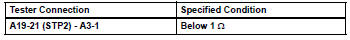

- Reconfirm dtc
- Clear the dtc (see page bc-47).
- Check if the same dtc is output (see page bc-47).
Result 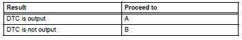


Replace abs and traction actuator assembly
 Master cylinder pressure sensor malfunction
Description
The master cylinder pressure sensor is connected to the skid control ecu in
the abs and traction
actuator.
Dtc c1281/81 can be detected when the master cylinder pressure sensor ...
 Open in pump motor circuit
Description
The motor relay drives the pump motor based on a signal from the skid control
ecu.
Wiring diagram
Refer to dtc c0273/13, c0274/14, c1361/91 (see page bc-79).
Inspection proce ...
Other materials:
Adjusting the settings manually
To adjust the fan speed, press
on
to increase the fan
speed and to
decrease the fan speed.
Press to turn the fan off.
To adjust the temperature setting, turn
clockwise to
increases the temperature and turn
counterclockwise to
...
Emission control system
Parts location
System diagram
On-vehicle inspection
Check fuel cut rpm
Increase the engine speed to at least 3,500 rpm.
Use a sound scope to check for injector operating
noise.
Check that the operating sounds stop momentarily
and then resume when the t ...
Short in front passenger side - side squib circuit
Description
The front passenger side - side squib circuit consists of the center airbag
sensor and the front seat side
airbag rh.
The circuit instructs the srs to deploy when the deployment conditions are met.
These dtcs are recorded when a malfunction is detected in the front passenge ...
