Toyota RAV4 (XA40) 2013-2018 Service Manual: Short in front passenger side - side squib circuit
Description
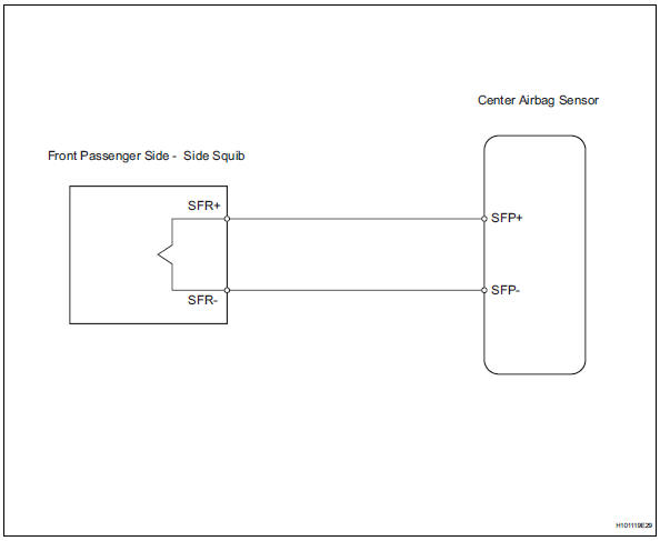
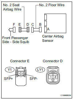
The front passenger side - side squib circuit consists of the center airbag sensor and the front seat side airbag rh.
The circuit instructs the srs to deploy when the deployment conditions are met.
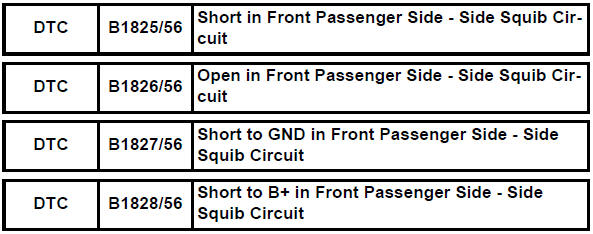
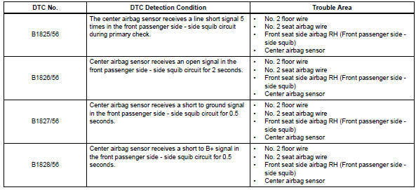
These dtcs are recorded when a malfunction is detected in the front passenger side - side squib circuit.
Wiring diagram
Inspection procedure
Hint:
- Perform the simulation method by selecting the "check mode" (signal check) with the intelligent tester (see page rs-52).
- After selecting the "check mode" (signal check), perform the simulation method by wiggling each connector of the airbag system or driving the vehicle on a city or rough road (see page rs-52).
- Check front seat side airbag assembly rh (front passenger side - side squib)
- Turn the ignition switch off.
- Disconnect the cable from the negative (-) battery terminal, and wait for at least 90 seconds.
- Disconnect the connector from the front seat side airbag rh.
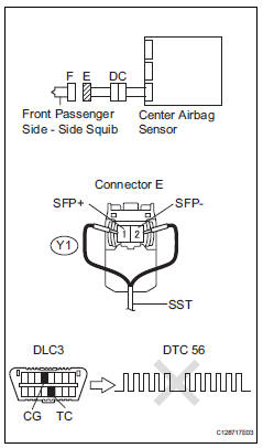
- Connect the black wire side of sst to connector c.
Caution:
Never connect a tester to the front seat side airbag rh (front passenger side - side squib) for measurement, as this may lead to a serious injury due to airbag deployment.
Notice:
- Do not forcibly insert sst into the terminals of the connector when connecting.
- Insert sst straight into the terminals of the connector.
Sst 09843-18060
- Connect the cable to the negative (-) battery terminal, and wait for at least 2 seconds.
- Turn the ignition switch on, and wait for at least 60 seconds.
- Clear the dtcs (see page rs-49).
- Turn the ignition switch off
- Turn the ignition switch on, and wait for at least 60 seconds.
- Check the dtcs (see page rs-49).
Ok: dtc b1825, b1826, b1827, b1828 or 56 is not output.
Hint:
Dtcs other than dtc b1825, b1826, b1827, b1828 or 56 may be output at this time, but they are not related to this check.

- Check connector
- Turn the ignition switch off.
- Disconnect the cable from the negative (-) battery terminal, and wait for at least 90 seconds.
- Disconnect sst from connector e.
- Check that the no. 2 Seat airbag wire connectors (on the front passenger side - side squib) are not damaged.
Ok: lock button is not disengaged, and claw of lock is not deformed or damaged.

- Check no. 2 Floor wire (front passenger side - side squib circuit)
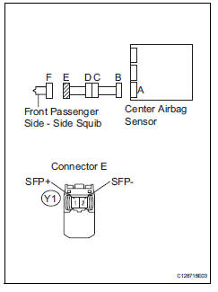
- Disconnect the connector from the center airbag sensor.
- Connect the cable to the negative (-) battery terminal, and wait for at least 2 seconds.
- Turn the ignition switch on.
- Measure the voltage of the wire harness side connector.
Standard voltage 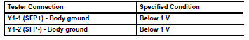
- Turn the ignition switch off
- Disconnect the cable from the negative (-) battery terminal, and wait for at least 90 seconds.
- Measure the resistance of the wire harness side connector.
Standard resistance 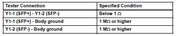
- Release the activation prevention mechanism built into connector b (see page rs-37).
- Measure the resistance of the wire harness side connector.
Standard resistance 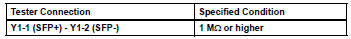

- Check no. 2 Seat airbag wire
- Disconnect the no. 2 Seat airbag wire from the no. 2 Floor wire.
- Connect the cable to the negative (-) battery terminal, and wait for at least 2 seconds.
- Turn the ignition switch off.
- Measure the voltage of the wire harness side connector.
Standard voltage 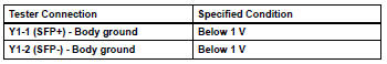
- Turn the ignition switch off.
- Disconnect the cable from the negative (-) battery terminal, and wait for at least 90 seconds
- Measure the resistance of the wire harness side connector.
Standard resistance 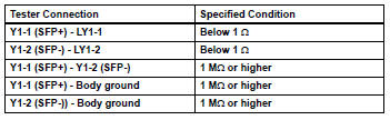

Repair or replace no. 2 Floor wire
 Short in front driver side - side squib circuit
Description
The driver side - side squib circuit consists of the center airbag sensor and
the front seat side airbag lh.
This circuit instructs the srs to deploy when the deployment conditio ...
 Short in driver side curtain shield squib circuit
Description
The driver side curtain shield squib circuit consists of the center airbag
sensor and the curtain shield
airbag lh.
The circuit instructs the srs to deploy when the deployment c ...
Other materials:
Problem symptoms table
Hint:
Use the table below to help determine the cause of the
problem symptom. The potential causes of the symptoms are
listed in order of probability in the "suspected area" column of
the table. Check each symptom by checking the suspected
areas in the order they are listed. Replace p ...
Lost communication with front satellite sensor bus lh
Description
The front airbag sensor lh consists of the diagnostic circuit and the frontal
deceleration sensor.
If the center airbag sensor receives signals from the frontal deceleration
sensor, it determines whether or
not the srs should be activated.
Dtc b1607/84, b1608/84, b1617/84 ...
Oxygen sensor circuit
Description
In order to obtain a high purification rate of the carbon monoxide (co),
hydrocarbon (hc) and nitrogen
oxide (nox) components in the exhaust gas, a twc is used. For the most efficient
use of the twc, the
air-fuel ratio must be precisely controlled so that it is always close to ...
