Toyota RAV4 (XA40) 2013-2018 Service Manual: Installation (2006/01- )
- Install front drive shaft assembly lh
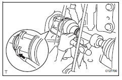
- Coat the spline of the inboard joint shaft with gear oil.
- Align the shaft splines and tap in the drive shaft with a brass bar and hammer.
Notice:
- Set the snap ring with the opening side facing downwards.
- Be careful not to damage the oil seal, boot and dust cover.
- Install front drive shaft assembly rh
- Coat the spline of the inboard joint shaft with gear oil.
- Align the shaft splines and securely insert the drive shaft
Notice:
Do not damage the oil seal.
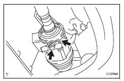
- Squeeze the ends of the bracket hole snap ring and install it to the bearing bracket.
- Install the bearing bracket bolt.
Torque: 32.4 N*m (330 kgf*cm, 24 ft.*Lbf)
- Connect steering knuckle with axle hub lh
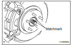
- Align the shaft splines in the drive shaft to the steering knuckle with axle hub, and connect the steering knuckle with axle hub.
- Connect steering knuckle with axle hub rh
Hint:
Use the same procedures described for the lh side.
- Connect front suspension lower no. 1 Arm sub-assembly lh (see page sp-24)
- Connect front suspension lower no. 1 Arm sub-assembly rh
Hint:
Use the same procedures described for the lh side.
- Install front stabilizer link assembly lh (see page sp-31)
- Install front stabilizer link assembly rh
Hint:
Use the same procedures described for the lh side.
- Install tie rod end sub-assembly lh (see page ps-45)
- Install tie rod end sub-assembly rh
Hint:
Use the same procedures described for the lh side.
- Connect front speed sensor lh
- Connect the speed sensor (see page bc-193).
- Connect front speed sensor rh
Hint:
Use the same procedures described for the lh side.
- Install front axle hub nut (see page ah-11)
- Install front wheel torque: 103 n*m (1,050 kgf*cm, 76 ft.*Lbf)
- Add automatic transaxle fluid
- Add automatic transaxle fluid for u140f (see page ax-152).
- Add automatic transaxle fluid for u241e (see page ax-151).
- Add automatic transaxle fluid for u151f (see page ax-178).
- Check for automatic transaxle fluid leakage
- Inspect and adjust front wheel alignment
- Inspect and adjust the front wheel alignment (see page sp-3).
 Installation
(2005/11-2006/01)
Installation
(2005/11-2006/01)
Install front drive shaft assembly lh
Coat the spline of the inboard joint shaft with gear
oil.
Using a brass bar and hammer, align the shaft
splines in the drive shaft.
Notice:
...
 Rear drive shaft assembly
Components
Removal
Hint:
Use the same procedures for the rh side and lh side.
The procedures listed below are for the lh side.
Disconnect cable from negative battery
terminal
Ca ...
Other materials:
All doors cannot be locked / unlocked simultaneously
Description
The main body ecu receives switch signals from the door control switch on the
power window regulator
master switch, door control switch and driver side door key cylinder, and
activates the door lock motor on
each door accordingly.
Wiring diagram
Inspection procedure
Perf ...
Front passenger side - side airbag sensor assembly initialization incomplete
Description
The side airbag sensor rh consists of parts including the diagnostic circuit
and the lateral deceleration
sensor.
When the center airbag sensor receives signals from the lateral deceleration
sensor, it determines
whether or not the srs should be activated.
Dtc b1628/82, ...
Insufficient coolant temperature for closed loop fuel control
Description
Refer to dtc p0115 (see page es-105).
Monitor description
The resistance of the ect sensor varies in proportion to the actual ect. The
ect supplies a constant
voltage to the sensor and monitors the signal output voltage of the sensor. The
signal voltage output
varies acc ...
