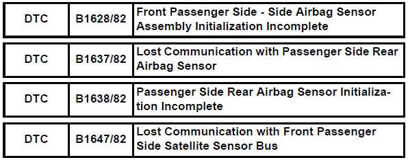
Toyota RAV4 (XA40) 2013-2018 Service Manual: Front passenger side - side airbag sensor assembly initialization incomplete
Description
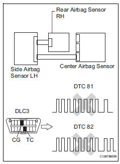
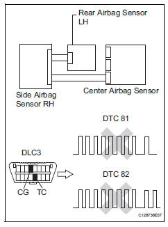
The side airbag sensor rh consists of parts including the diagnostic circuit and the lateral deceleration sensor.
When the center airbag sensor receives signals from the lateral deceleration sensor, it determines whether or not the srs should be activated.
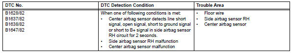
Dtc b1628/82, b1637/82, b1638/82 or b1647/82 is set when a malfunction is detected in the side airbag sensor rh circuit.
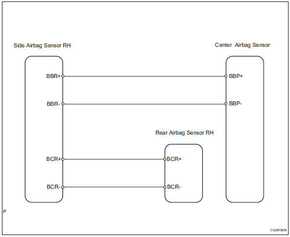
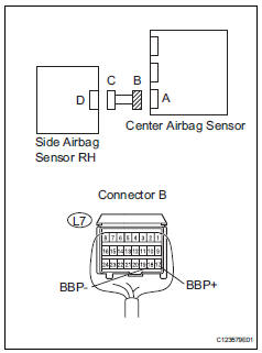
Wiring diagram
Inspection procedure
- Check connection of connector
- Turn the ignition switch off.
- Disconnect the cable from the negative (-) battery terminal, and wait for at least 90 seconds.
- Check that the connectors are properly connected to the center airbag sensor, rear airbag sensor rh and the side airbag sensor rh.
Ok: the connectors are properly connected.


- Check floor wire (open)
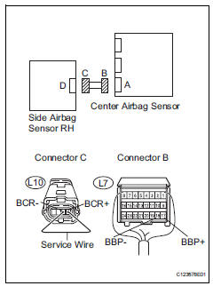
- Disconnect the connectors from the center airbag sensor and the side airbag sensor rh.
- Using a service wire, connect l10-4 (bbr+) and l10-3 (bbr-) of connector c.
Notice:
Do not forcibly insert the service wire into the terminals of the connector when connecting.
- Measure the resistance of the wire harness side connector.
Standard resistance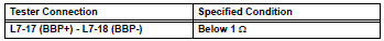

- Check floor wire (short)
- Disconnect the service wire from connector c.
- Measure the resistance of the wire harness side connector.
Standard resistance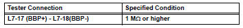

- Check floor wire (to b+)
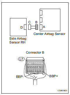
- Connect the cable to the negative (-) battery terminal, and wait for at least 2 seconds.
- Turn the ignition switch on.
- Measure the voltage of the wire harness side connector.
Standard voltage 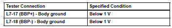


- Check floor wire (to ground)
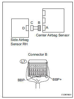
- Turn the ignition switch off.
- Disconnect the cable from the negative (-) battery terminal, and wait for at least 90 seconds.
- Measure the resistance of the wire harness side connector.
Standard resistance 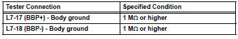


- Check floor wire (open)
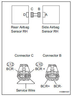
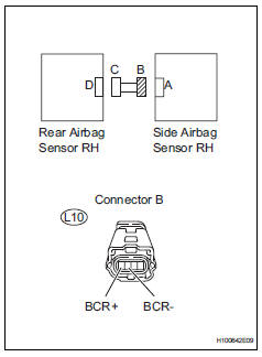
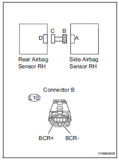
- Disconnect the connectors from the side airbag sensor rh and the rear airbag sensor rh.
- Using a service wire, connect l12-1 (bcr-) and l12-2 (bcr+) of connector c.
Notice:
Do not forcibly insert the service wire into the terminals of the connector when connecting.
- Measure the resistance of the wire harness side connector.
Standard resistance 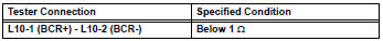

- Check floor wire (short)
- Disconnect the service wire from connector c.
- Measure the resistance of the wire harness side connectors.
Standard resistance 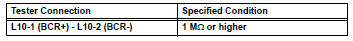

- Check floor wire (to b+)
- Connect the cable to the negative (-) battery terminal, and wait for at least 2 seconds.
- Turn the ignition switch on.
- Measure the voltage of the wire harness side connector.
Standard voltage 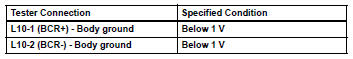

- Check floor wire (to ground)
- Turn the ignition switch off.
- Disconnect the cable from the negative (-) battery terminal, and wait for at least 90 seconds.
- Measure the resistance of the wire harness side connector.
Standard resistance 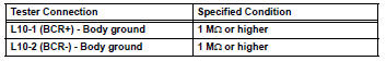

- Check side airbag sensor rh
- Connect the connectors to the center airbag sensor .
- Interchange the side airbag sensor lh with the side airbag sensor rh and connect the connectors to them.
- Connect the cable to the negative (-) battery terminal, and wait for at least 2 seconds
- Turn the ignition switch on, and wait for at least 60 seconds.
- Clear the dtcs (see page rs-49).
- Turn the ignition switch off.
- Turn the ignition switch on, and wait for at least 60 seconds.
- Check for dtcs (see page rs-49).
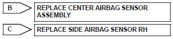
Result 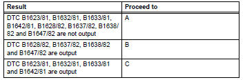
Hint:
Dtcs other than dtc b1623/81, b1632/81, b1633/81, b1642/81, b1628/82, b1637/82, b1638/82 and b1647/ 82 may be output at this time, but they are not related to this check.

- Check rear airbag sensor rh
- Turn the ignition switch off.
- Disconnect the cable from the negative (-) battery terminal, and wait for at least 90 seconds.
- Interchange the rear airbag sensor rh with the rear airbag sensor lh and connect the connectors to them.
- Connect the cable to the negative (-) battery terminal, and wait for at least 2 seconds
- Turn the ignition switch on, and wait for at least 60 seconds.
- Clear the dtcs (see page rs-49).
- Turn the ignition switch on, and wait for at least 60 seconds.
- Check the dtcs (see page rs-49).
Result 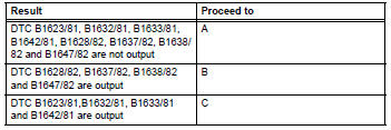

Use simulation method to check
 Lost communication with front passenger side - side airbag sensor assembly
Description
The side airbag sensor rh consists of parts including the diagnostic circuit
and the lateral deceleration
sensor.
When the center airbag sensor receives signals from the lateral ...
 Driver side rear airbag sensor circuit malfunction
Description
The rear airbag sensor lh consists of parts including the diagnostic circuit
and the lateral deceleration
sensor.
When the center airbag sensor receives signals from the lateral ...
Other materials:
Front brake
Components
Removal
Hint:
Use the same procedures for the lh side and rh side.
The procedures listed below are for the lh side.
Remove front wheel
Drain brake fluid
Notice:
Wash off brake fluid immediately if it comes in
contact with any painted surface.
Disconnec ...
Transmitter id
Description
The tire pressure warning valve and transmitter that is installed in the
tires and wheels measures the air
pressure of the tires. The measured values are transmitted to the tire pressure
warning receiver on the
body as radio waves and then sent to the tire pressure warning ecu ...
Terminals of ecu
Check power steering ecu
Hint:
Measurements cannot be performed on the c connector
side of the power steering ecu.
Measure the voltage and resistance of the
connectors.
If the result is not as specified, the ecu may have a
malfunction. ...
