Toyota RAV4 (XA40) 2013-2018 Service Manual: Front stabilizer bar
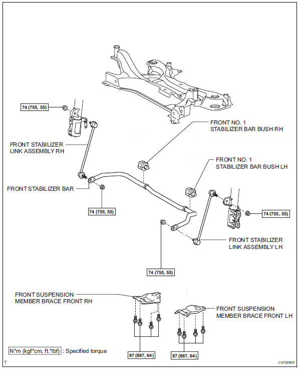
Components
Removal
- Remove front wheel
- Remove front stabilizer link assembly lh
- Remove the 2 nuts and stabilizer link.
- Remove front stabilizer link assembly rh
Hint:
Use the same procedures described for the lh side.
- Remove front suspension member brace front lh
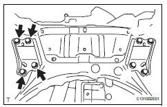
- Remove the 4 bolts and member brace from the corssmember.
- Remove front suspension member brace front rh
Hint:
Use the same procedures described for the lh side.
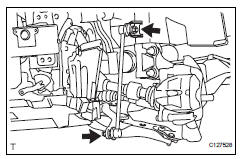
- Remove front stabilizer bar
- Remove the stabilizer bar from the crossmember.
- Remove front no. 1 Stabilizer bar bush lh
- Remove the bush from the stabilizer bar.
- Remove front no. 1 Stabilizer bar bush rh
Hint
Use the same procedures described for the lh side.
Inspection
- Inspect front stabilizer link assembly lh
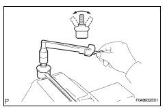
- As shown in the illustration, move the ball joint stud back and forth 5 times before installing the nut.
- Using a torque wrench, turn the nut continuously at a rate of 3 to 5 seconds per turn and take the torque reading on the fifth turn.
Turning torque: 0.05 To 1.96 N*m, (0.5 To 20 kgf*cm, 0.4 To 17 in.*Lbf) or less
- Check for any cracks and grease leaks on the ball joint dust cover.
Installation
- Install front no. 1 Stabilizer bar bush lh
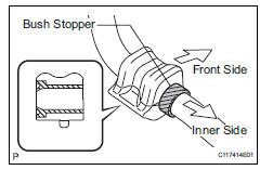
- Install the bush.
Hint:
- Install each bush to the inner side of each bush stopper on the stabilizer bar.
- Install each bush with its slit facing the vehicle rear side.
- Remove front no. 1 Stabilizer bar bush rh
Hint:
Use the same procedures described for the lh side.
- Install front stabilizer bar
- Install the stabilizer bar to the crossmember.
- Install front suspension member brace front lh
- Install the member brace with the 4 bolt to the suspension member.
Torque: 87 n*m (887 kgf*cm, 64 ft.*Lbf)
- Install front suspension member brace front rh
Hint:
Use the same procedures described for the lh side.
- Install front stabilizer link assembly lh
- Install the link with the 2 nut.
Torque: 74 n*m (755 kgf*cm, 55 ft.*Lbf)
- Install front stabilizer link assembly rh
Hint:
Use the same procedures described for the lh side.
- Install front wheel torque: 103 n*m (1,050 kgf*cm, 76 ft.*Lbf)
- Stabilize suspension (see page sp-12)
 Front lower ball joint
Components
Removal
Hint:
Use the same procedures for the rh side and lh side.
The procedures listed below are for the lh side.
Remove front wheel
Remove front speed sensor lh (for ...
 Rear coil spring
Components
Removal
Hint:
Use the same procedures for the rh side and lh side.
The procedures listed below are for the lh side.
Remove rear wheel
Remove skid control sensor wire (fo ...
Other materials:
Display settings
Settings are available for adjusting the contrast and brightness
of the screen.
Screen for display settings
Press the “setup” button.
Select “display” on the “setup” screen.
Adjust the screen display
Adjust the camera display*
Changes to day mode.
*: If equipped
...
General maintenance (2005/11-2006/01)
Inspect steering linkage and gear housing
Check the steering wheel free play.
Check the steering linkage for looseness or
damage.
Check that the tie rod ends do not have
excessive play
Check that the dust seals and boots are not
damaged.
Check that the boot clamps are not ...
Disassembly (2006/01- )
Remove front axle inboard joint boot no. 2
Clamp
One touch type:
using a screwdriver, remove the no. 2 Inboard joint
boot clamp, as shown in the illustration.
Claw engagement type:
using needle-nose pliers, remove the no. 2 Inboard
joint boot clamp, as shown in the illustra ...
