Toyota RAV4 (XA40) 2013-2018 Service Manual: Front lower ball joint
Components
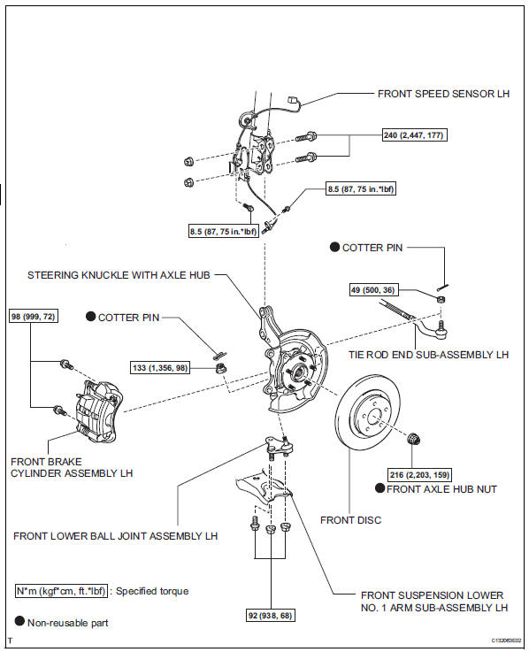
Removal
Hint:
- Use the same procedures for the rh side and lh side.
- The procedures listed below are for the lh side.
- Remove front wheel
- Remove front speed sensor lh (for 2wd) (see page bc-191)
- Remove front brake cylinder assembly lh (see page br-40)
- Remove front disc (see page br-42)
- Remove front axle hub nut (see page ah-6)
- Disconnect front suspension lower no. 1 Arm sub-assembly lh (see page ah-7)
- Disconnect tie rod end sub-assembly lh (see page ps-42)
- Remove steering knuckle with axle hub (see page ah-7)
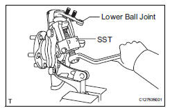
- Remove front lower ball joint assembly lh
- Remove the cotter pin and nut.
- Using sst, remove the lower ball joint.
Sst 09628-62011
Inspection
- Inspect front lower ball joint assembly lh
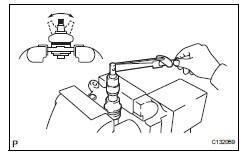
- As shown in the illustration, move the ball joint stud back and forth 5 times before installing the nut.
- Using a torque wrench, turn the nut continuously at a rate of 3 to 5 seconds per turn and take the torque reading on the fifth turn.
Standard turning torque: 0.98 To 3.43 N*m (10 to 35 kgf*cm, 9 to 30 in.*Lbf) or less
- Check for any cracks and grease leaks on the ball joint dust cover.
Installation
Hint:
- Use the same procedures for the rh side and lh side.
- The procedures listed below are for the lh side.
- Install front lower ball joint assembly lh
- Install the ball joint with the 2 bolts and nut to the lower arm.
Torque: 92 n*m (938 kgf*cm, 68 ft.*Lbf)
- Install the lower ball joint with the nut to the steering knuckle.
Torque: 133 n*m (1,360 kgf*cm, 98 ft.*Lbf)
- Install a new cotter pin.
If the holes for the cotter pin are not aligned, tighten the nut further up to 60°.
- Install steering knuckle with axle hub (see page ah-9)
- Connect front suspension lower no. 1 Arm sub-assembly lh (see page ah-10)
- Connect tie rod end sub-assembly lh (see page ps-45)
- Install front disc (see page br-43)
- Install front disc brake cylinder assembly lh (see page br-46)
- Install front axle hub nut (see page ah-10)
- Install front speed sensor lh (see page bc- 193)
- Install front wheel torque: 103 n*m (1,050 kgf*cm, 76 ft.*Lbf)
- Inspect and adjust front wheel alignment
- Inspect and adjust the front wheel alignment (see page sp-3).
 Front suspension lower no. 1 Arm
Components
Removal
Remove front wheel
Remove hood sub-assembly
Remove the hood (see page ed-4).
Suspend engine assembly
Install the no. 1 And no. 2 Engine hangers with the ...
 Front stabilizer bar
Components
Removal
Remove front wheel
Remove front stabilizer link assembly lh
Remove the 2 nuts and stabilizer link.
Remove front stabilizer link assembly rh
Hint:
Use ...
Other materials:
Inspection
Inspect oil pump assembly
Turn the drive gear with 2 screwdrivers and make
sure it rotates smoothly.
Notice:
Be careful not to damage the oil seal lip.
Inspect clearance of oil pump assembly
Push the driven gear to one side of the body. Using
a feeler gauge, measur ...
General maintenance
Listed below are the general maintenance items that should be
performed at the intervals specified in the “owner’s warranty
information booklet” or “owner’s manual supplement/scheduled
maintenance guide”. It is recommended that any problem
you notice should be brought to the attentio ...
Occupant classification ecu malfunction
Description
Dtc b1795 is recorded when a malfunction is detected in the occupant
classification ecu.
Troubleshoot dtc b1771 first when dtc b1771 and b1795 are output simultaneously.
Wiring diagram
Inspection procedure
Check for dtc
Turn the ignition switch on, and wait ...
