Toyota RAV4 (XA40) 2013-2018 Service Manual: Door control transmitter module
Components
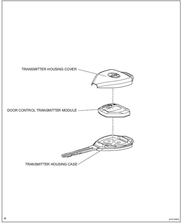
Removal
- Remove transmitter housing cover
Notice:
Take extra care when handling these precision electronic components.
- Twist the screwdriver in the direction of the arrow mark in the illustration, and open the transmitter housing cover.
Notice:
Do not forcibly pry the cover.
Hint:
Tape the screwdriver tip before use.
- Remove door control transmitter module
Inspection
- Inspect door control transmitter module
- Inspect operation of the transmitter.
- emove the battery (lithium battery: cr2016) from the transmitter.
- Install a new or non-depleted battery (lithium battery: cr2016).
Hint:
When a new or non-depleted battery is not available, first connect 2 new 1.5 V batteries in series. Then connect leads to the batteries and use the leads to apply 3 v to the transmitter, as shown in the illustration
- From outside the vehicle, approximately 1 m (3.28 Ft.) From the driver side outside door handle, test the transmitter by pointing its key plate at the vehicle and pressing a transmitter switch.
Ok: door lock can be operated via the transmitter. Led illuminates more than Once.
Hint:
- The operating range differs depending on the user, the way the transmitter is held and the location.
- The transmitter's faint electric waves may be affected if the area has strong electric waves or noise. The transmitter's operating range may be shortened or the transmitter may not function.
- Inspect the battery capacity.
Hint:
- When checking the amount of energy left in the battery, the battery must be checked while it is installed in the transmitter (a resistance of 1.2 Kù is applied to the battery). When the battery energy is checked by itself (uninstalled), the voltage reading will be more than 2.5 V until the energy is depleted.
- If the transmitter is malfunctioning, the voltage reading of the energy left in the battery will be inaccurate.
- Remove the battery from the transmitter.
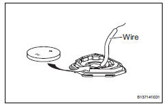
- Connect a wire to the negative (-) terminal of the transmitter and install the battery.
- Connect the tester's positive (+) lead to the battery and the negative (-) lead to the wire.
- Press one of the transmission switches on the transmitter for approximately 1 second.
- Press the transmission switch on the transmitter again to check the voltage.
Standard voltage: 2.2 V or higher
Hint:
- When the temperature of the battery is low,
the inspection result will not be accurate.
When the inspection result is less than 2.2 V, conduct the test again after leaving the battery in a place with a temperature of 18? (64?) for more than 30 minutes.
- Read the voltage immediately after the
switch is pressed. When 0.8 Seconds have
passed after the switch is pressed, the
automatic power off function starts and
resistance applied to the battery will cease.
The voltage of the battery will be 2.5 V or more.
- Press the switch at least 3 times before reading the voltage. If the battery temperature has just returned to 18? (64?), the voltage may be unusually high for the first or second voltage reading.
Installation
- Install door control transmitter module
Notice:
Take extra care when handling these precision electronic components.
- Install transmitter housing cover
- Install the transmitter housing cover to the transmitter housing case.
- Check that the transmitter's led illuminates 3 times when the switch is pressed 3 times.
Ok: transmitter's led illuminates 3 times when switch is pressed 3 times.
 Data list / active test
Read data list
Hint:
Using the intelligent tester's data list allows switch,
actuator and other item values to be read without
removing any parts. Reading the data list early in
troubleshoot ...
 Door control switch
Inspection
Inspect power window regulator master
switch assembly (door control switch)
Measure the resistance of the door control switch.
Standard resistance
If the result is not ...
Other materials:
Rear occupant classification sensor lh circuit malfunction
Description
The rear occupant classification sensor lh circuit consists of the occupant
classification ecu and the rear
occupant classification sensor lh.
Dtc b1782 is recorded when a malfunction is detected in the rear occupant
classification sensor lh
circuit.
Wiring diagram
...
Headlight relay circuit
Description
When the light control switch, located on the headlight dimmer switch, is
turned to the head position, the
head relay illuminates the headlights.
Wiring diagram
Inspection procedure
Perform active test by intelligent tester (headlight)
Connect the intelligent tester ( ...
Thermostat
Components
Removal
Remove no. 1 Engine under cover
Drain engine coolant (see page co-6)
Remove radiator support opening cover
Disconnect no. 2 Radiator hose
Remove water inlet
Remove the 2 nuts and disconnect the water inlet
from the cylinder block.
Remove thermostat
...
