Toyota RAV4 (XA40) 2013-2018 Service Manual: Camshaft position "a" actuator circuit (bank 1)
Dtc
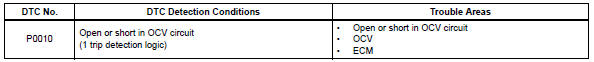
P0010 Camshaft position "a" actuator circuit (bank 1)
Description
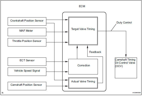
The variable valve timing (vvt) system includes the ecm, ocv and vvt controller. The ecm sends a target duty-cycle control signal to the ocv. This control signal regulates the oil pressure supplied to the vvt controller. Camshaft timing control is performed according to engine operating conditions such as the intake air volume, throttle valve position and engine coolant temperature. The ecm controls the ocv, based on the signals transmitted by several sensors. The vvt controller regulates the intake camshaft angle using oil pressure through the ocv. As a result, the relative positions of the camshaft and crankshaft are optimized, the engine torque and fuel economy improve, and the exhaust emissions decrease under overall driving conditions. The ecm detects the actual intake valve timing using signals from the camshaft and crankshaft position sensors, and performs feedback control. This is how the target intake valve timing is verified by the ecm.
Hint:
This dtc relates to the oil control valve (ocv).
Monitor description
The ecm optimizes the valve timing using the vvt system to control the intake camshaft. The vvt system includes the ecm, the ocv and the vvt controller. The ecm sends a target duty-cycle control signal to the ocv. This control signal regulates the oil pressure supplied to the vvt controller. The vvt controller can advance or retard the intake camshaft.
After the ecm sends the target duty-cycle control signal to the ocv, the ecm monitors the ocv current to establish an actual duty-cycle. The ecm determines the existence of a malfunction and sets the dtc when the actual duty-cycle ratio varies from the target duty-cycle ratio.
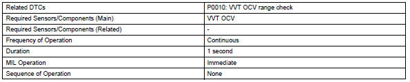
Monitor strategy
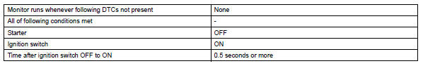
Typical enabling conditions
Typical malfunction thresholds
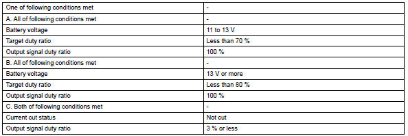
Component operating range
![]()
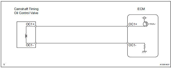
Wiring diagram
Inspection procedure
Hint:
Read freeze frame data using the intelligent tester. Freeze frame data records the engine condition when malfunctions are detected. When troubleshooting, freeze frame data can help determine if the vehicle was moving or stationary, if the engine was warmed up or not, if the air-fuel ratio was lean or rich, and other data from the time the malfunction occurred.
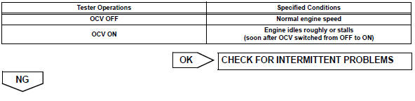
- Perform active test using intelligent tester (operate ocv)
- Connect the intelligent tester to the dlc3.
- Start the engine and turn the tester on.
- Warm up the engine.
- On the tester, select the following menu items: diagnosis / enhanced obd ii / active test / vvt ctrl b1.
- Check the engine speed while operating the oil control valve (ocv) using the tester.
Ok
- Inspect camshaft timing oil control valve assembly
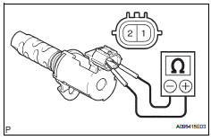
- Disconnect the b17 ocv connector.
- Measure the resistance between the terminals of the ocv.
Standard resistance: 6.9 To 7.9 ٠at 20°c (68°f)
- Reconnect the ocv connector.

- Check harness and connector (ocv - ecm)
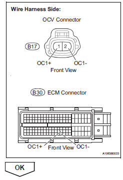
- Disconnect the b17 ocv connector.
- Disconnect the b30 ecm connector.
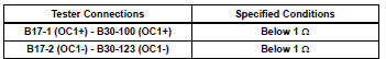
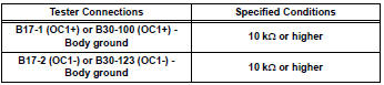
- Measure the resistance of the wire harness side connectors.
Standard resistance (check for open)
Standard resistance (check for short)
- Reconnect the ocv connector.
- Reconnect the ecm connector.
 Diagnostic trouble code chart
Hint:
Parameters listed in the chart may be different than your
readings depending on the type of instrument and other
factors.
If any dtcs are displayed during a check mode dtc check,
check th ...
 Camshaft position "A"
Dtc P0011 Camshaft position
"a" - timing over-advanced or system performance (bank 1)
Dtc P0012 Camshaft
position "a" - timing over-retarded (bank 1)
Description
The v ...
Other materials:
Removal
Disconnect cable from negative battery
terminal
Caution:
Wait at least 90 seconds after disconnecting the
cable from the negative (-) battery terminal to
prevent airbag and seat belt pretensioner activation.
Remove steering column cover lower
Detach the 4 claws, release the ...
Installation
Install fan and generator v belt
Using sst and 19 mm socket wrench, loosen the vribbed
belt tensioner arm clockwise, then install the
fan and generator v belt.
Sst 09216-42010
Notice:
Be sure to connect sst and the tools so that
they are in line during use.
When retracti ...
Horn relay
On-vehicle inspection
Remove engine room no. 1 Relay block cover
Inspect integration relay (unit a: horn relay)
Using a screwdriver, detach the 2 claws and
disconnect the integration relay from the engine
room junction block.
Hint:
Tape the screwdriver tip before use.
Mea ...
