Toyota RAV4 (XA40) 2013-2018 Service Manual: Wiper switch
Precaution
- Precaution for vehicle with srs
- Some procedures in this section may affect the supplemental restraint system (srs). Prior to performing the procedures, read the srs section's "precaution" (see page ss-2).
Components

Removal
- Disconnect cable from negative battery terminal
Caution:
Wait at least 90 seconds after disconnecting the cable from the negative (-) battery terminal to prevent airbag and seat belt pretensioner activation.
- Place front wheels facing straight ahead
- Remove steering pad assembly (see page rs- 336)
- Remove steering wheel assembly (see page sr-12)
- Remove steering column cover upper (see page sr-12)
- Remove steering column cover lower (see page sr-12)
- Remove wiper and washer switch assembly

- Disconnect the connectors.
- Detach the claw and remove the wiper switch.
Notice:
Do not push the claw with excessive force as damage may occur.
Inspection
- Inspect windshield wiper switch assembly

- Check the front wiper switch.
- Measure the resistance of the switch.
Standard resistance 
If the result is not as specified, replace the switch assembly.
- Check the front washer switch assembly.
- Measure the resistance of the switch.
Standard resistance 
If the result is not specified, replace the switch assembly.
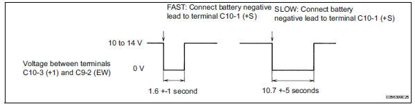
- Check the intermittent operation.
- Connect the voltmeter's positive (+) lead to terminal e10-3 (+1) and the negative (-) lead to terminal e9-2 (ew).
- Connect the battery's positive (+) lead to terminal e10-2 (+b) and the negative (-) lead to terminal e9-2 (ew) and e10-1 (+s).
- Turn the wiper switch to the int position.
- Connect the battery's positive (+) lead to terminal e10-1 (+s) for 5 seconds.
- Connect the battery's negative (-) lead to terminal e10-1 (+s). Operate the intermittent wiper relay and check the voltage between terminals e10-3 (+1) and e9-2 (ew).
Standard voltage: refer to the illustration below.
If the result is not as specified, replace the switch assembly.
- Check the front washer operation.
- Turn the wiper switch off.
- Connect the battery's positive (+) lead to terminal e10-2 (+b) and the negative (-) lead to terminals e10-4 (+s) and e9-2 (ew).
- Connect the voltmeter's positive (+) lead to e10-3 (+1) and the negative (-) lead to terminal e9-2 (ew).
- Turn the washer switch on and off, and check the voltage between terminals e10-3 (+1) and e9-2 (ew).
Ok: refer to the illustration below.

If the result is not as specified, replace the switch assembly.
- check the rear wiper switch.

- Measure the resistance of the switch.
Standard resistance 
If the result is not as specified, replace the switch assembly.
- Check the rear washer switch.
- Measure the resistance of the switch.
Standard resistance 
If the result is not as specified, replace the switch assembly.
Installation
- Install wiper and washer switch assembly

- Attach the claw to install the wiper switch.
- Connect the connectors.
Notice:
Do not push the claw with excessive force as damage may occur.
- Install steering column cover lower (see page sr-20)
- Install steering column cover upper (see page sr-20)
- Install steering wheel assembly (see page sr-21)
- Place front wheels facing straight ahead
- Inspect steering wheel center point
- Install steering pad assembly (see page rs- 336)
- Connect cable to negative battery terminal
- Inspect steering pad assembly (see page rs- 337)
- Check srs warning light
- Check the srs warning light (see page rs-337).
 Rear wiper rubber
Components
Removal
Remove rear wiper blade assembly
Rotate and remove the cap as described in the
"remove" procedures.
Raise the arm and blade.
Raise the wip ...
 Washer motor
Components
Removal
Disconnect cable from negative battery
terminal
Caution:
Wait at least 90 seconds after disconnecting the
cable from the negative (-) battery terminal to
prevent ai ...
Other materials:
Footwell light
On-vehicle inspection
Inspect footwell light
Connect the battery's positive (+) lead to terminal 2
and the negative (-) lead to terminal 1, then check
that the light comes on.
Ok:
light comes on.
If the result is not as specified, replace the light. ...
Solar sensor (for automatic air conditioning system)
Components
Removal
Disconnect cable from negative battery
terminal
Caution:
Wait at least 90 seconds after disconnecting the
cable from the negative (-) battery terminal to
prevent airbag and seat belt pretensioner activation.
Remove solar sensor
Using a screwdriver, p ...
Operating HomeLink
Press the appropriate
HomeLink button. The
HomeLink indicator light
should turn on.
The status of the opening and
closing of a garage door is
shown by the garage door operation
indicators.
Vehicles with auto anti-glare
inside rear view mirror
Opening
Closing
Vehicles with Digital Rearview
Mirr ...
