Toyota RAV4 (XA40) 2013-2018 Service Manual: Reassembly
- Bearing position

Standard bearing position

- Install differential gear lube apply tube

- Install the apply tube and clamp to the transaxle
housing with the bolt.
Torque: 9.8 N*m (100 kgf*cm, 87 in.*Lbf)
Notice:
Make sure to insert the pipe to the stopper.
- Install underdrive output shaft oil seal ring

- Install a new oil seal ring to the transaxle housing.
- Install underdrive cylindrical roller bearing

- Using sst and a press, press in the underdrive cylindrical roller bearing.
Sst 09950-60020 (09951-00810), 09950-70010 (09951-07100)
Notice:
Do not apply excessive pressure.
- Install underdrive clutch drum oil seal ring

- Install 2 new oil seal rings to the transaxle.
- Install underdrive brake piston
- Wind a vinyl tape around sst at the place 4.0 Mm (0.157 In.) Above from the bottom end until the thickness of the wound tape is about 5.0 Mm (0.197 In.)

Sst 09950-60010 (09951-00320)
Notice:
Clean sst to remove deposited oil before winding a vinyl tape.

- Using sst and a press, press in the needle-roller bearing to the transaxle until the wound vinyl tape contacts the transaxle case.
Sst 09950-60010 (09951-00320), 09950-70010 (09951-07100)

- Coat 2 new o-rings with atf, and install them to the underdrive brake piston.

- Install the underdrive brake piston to the transaxle.
- Using sst, a snap ring expander and press, press in the piston return spring and snap ring to the transaxle.
Notice:
Do not apply excessive pressure.

- Install no. 2 Breather plug
- Install counter drive gear hole snap ring

- Using a screwdriver, press in the snap ring to the transaxle.
- Install counter drive gear

- Using sst and a press, press in the 2 bearings outer races to the transaxle.
Sst 09950-60020 (09951-00890), 09950-70010 (09951-07150)

- Using sst and a press, press in the tapered roller bearing to the counter drive gear until the bearing race contacts with the snap ring.
Notice:
Do not apply excessive pressure.
Sst 09649-17010
- Using sst and a press, install the counter drive gear and bearing to the transaxle.
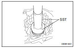
Sst 09950-70010 (09951-07150), 09950-60020 (09951-00750)
Notice:
Do not apply excessive pressure.
- Install 1st and reverse brake piston

- Coat 2 new o-rings with atf.
- Install the 2 o-ring to the 1st and reverse brake piston.

- Coat the 1st and reverse brake piston with atf, and install it to the transaxle.
- Install 1st and reverse brake return spring sub-assembly

- Using sst, a press and snap ring expander, press the piston return spring and snap ring to the transaxle.
Sst 09387-00070
Notice:
- Stop the press when the spring sheet is lowered to the place 1 to 2 mm (0.039 To 0.078 In.) From the snap ring groove, preventing the spring sheet from being deform.
- Do not expand the snap ring excessively.
- Install front planetary ring gear

- Using a screwdriver, install the front planetary ring gear and snap ring to the brake hub.
- Install front planetary gear assembly

- Install the front planetary gear assembly to the brake hub.

- Using sst and a press, press-fit the front planetary gear.
Sst 09950-60010 (09951-00500), 09950-70010 (09951-07100)
Notice:
Do not apply excessive pressure.

- Install the washer, as shown in the illustration.

- Using sst, install the nut.
Sst 09387-00030, 09387-00080
Torque: 280 n*m (2,855 kgf*cm, 206 ft.*Lbf)

- Using sst and a torque wrench, measure the turning torque of the bearing while rotating sst at 60 rpm. When the measured value is not within the specified value, gradually tighten the nut until it reaches the specified value.
Sst 09387-00080
Torque: turning torque at 60 rpm
0.51 To 1.02 N*m (5.1 To 10.0 Kgf*cm, 4.4
To 8.7 In.*Lbf) for new
0.3 To 0.5 N*m (3.1 To 5.1 Kgf*cm, 27 to 4.4 In.*Lbf) for used
Hint:
Use a torque wrench with a fulcrum length of 160 mm (6.3 In.).

- Using a chisel and hammer, stake the front planetary gear washer.
- Install input sun gear

- Install the 2 thrust bearings, bearing race and front planetary sun gear to the front planetary gear.
Standard bearing and race diameter

- Install rear planetary gear assembly
- Coat the bearing race with atf, and install it to the rear planetary gear assembly.

Standard bearing race diameter 
- Install the no. 2 Thrust washer.
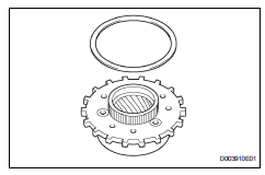
- Install the rear planetary gear to the rear planetary ring gear.

- Using a screwdriver, install the snap ring.

- Install 1st and reverse brake clutch disc

- Install the 5 plates and 5 discs.
Install in order: p - d - p - d - p - d - p - d - p - d
Hint:
P = plate
D = disc
- Using a vernier caliper, measure the distance between the disc surface and the contact surface of the 2nd brake cylinder and transaxle (dimension a).
- Select an appropriate flange so that the pack
clearance will meet the specified value.
0.745 To 1.21 Mm (0.0293 To 0.0476 In.)
Hint:
Piston stroke = dimension a - flange thickness

Standard flange thickness 

- Install the flange.
- Install 2nd brake piston assembly

- Install the 2nd brake piston to the transaxle.
- Install the snap ring and measure the inside diameter.
Standard inside diameter: more than 167 mm (6.57 In.)
Notice:
- Because the taper snap ring has the positioning direction, check it when installing.
- When the diameter does not satisfy the specified value, replace the snap ring with a new one.
- Install 1-way clutch sleeve outer

- Install the 1-way clutch outer sleeve to the 2nd brake cylinder.
Notice:
Check the positioning direction of the outer sleeve.
- Install 1-way clutch assembly

- Install the inner race to the 1-way clutch.
Notice:
Check the direction of the inner race.

- Check the rotating direction of the 1-way clutch for the lock or free operation, as shown in illustration.

- Install the 1-way clutch and bearing to the 1-way clutch sleeve outer.
Standard bearing diameter 
Notice:
Install the thrust bearing properly so that nocolored race will be visible.
- Install rear planetary sun gear assembly

- Coat the no. 1 Thrust washer with petroleum jelly, and install it onto the rear planetary sun gear.

- Coat the bearing with petroleum jelly, and install it onto the rear planetary sun gear.
Standard bearing diameter 

- Install the rear planetary sun gear to the rear planetary gear.
- Install 2nd brake clutch disc

- Install the 3 discs and 3 plates to the transaxle.
Standard install in order: p - d - p - d - p - d
Hint:
P = plate
D = disc
- Temporarily install the snap ring.

- Using a vernier caliper, measure the distance between the disc surface and snap ring surface.
- Select an appropriate flange so that the pack clearance will meet the specified value.
Standard pack clearance: 0.50 To 0.91 Mm (0.0197 To 0.0358 In.)
Hint:
Piston stroke = clearance - flange thickness - snap ring thickness 1.6 Mm (0.063 In.)
Standard flange thickness 

- Temporarily remove the snap ring, attach the selected flange and restore the snap ring.
Selected flange and restore the snap ring.
Notice:
Secure the snap ring so that its gap is visible through the groove of the transaxle case.
- Install direct clutch

- Install the bearing race to the direct clutch.
Standard bearing race diameter 
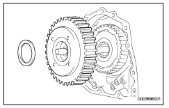
- Install the direct clutch and thrust bearing to the rear planetary sun gear.
Notice:
The disc in the direct clutch should completely mate with the hub attached outside the rear planetary sun gear. Otherwise, the rear cover cannot be installed.

- Clean the connector part of the transaxle case and rear cover.
- As shown in the illustration, place a straightedge on the direct clutch drum and measure the distance between the transaxle case and the straightedge using a vernier caliper (dimension b).

- Measure the 2 places of the rear cover as shown in the illustration. Calculate a dimension c using the following formula.
Hint:
Dimension c = dimension (1) - dimension (2)
- Calculate the end play value using the following formula. Select a thrust bearing which satisfies the end play value and install it.
End play: 0.198 To 0.936 Mm (0.00780 To 0.03685 In.)
Notice:
Make sure that the colored race side is facing the direct clutch assembly.
Hint:
End play = dimension c - dimension b
Standard bearing thickness and diameter

- Install no. 1 Governor apply gasket

- Install 2 new governor apply gaskets.
- Install front clutch apply tube

- Install the clamp to the front clutch apply tube.
Notice:
Make sure to install the clamp to the apply pipe before installing the apply pipe to the transaxle case. This prevents the apply pipe from being deformed or damaged.
- Install brake apply tube

- Install the clamp to the brake apply tube.
Notice:
Make sure to install the clamp to the apply pipe before installing the apply pipe to the transaxle case. This prevents the apply pipe from being deformed or damaged.

- Install the 2 apply tubes and to the transaxle with the bolt.
Torque: 5.4 N*m (55 kgf*cm, 48 in.*Lbf)
Notice:
Each pipe should be securely inserted until it reaches the stopper.
- Install no. 1 Transaxle case plug

- Install 2 new o-rings to the 2 plugs.
- Install the 2 plugs to the transaxle rear cover.
Torque: 7.4 N*m (75 kgf*cm, 65 in.*Lbf)
- Install transaxle rear cover subassembly

- Using sst and a press, press in the bearing.
Sst 09950-60010 (09951-00230, 09952-06010)
Standard depth: 12.05 To 12.75 Mm (0.4744 To 0.5020 In.)
Notice:
- Face the inscribed mark side of the bearing race up.
- Repeat the press-fit until the specified value is obtained.
- Apply adhesive to the 2 screws.
Adhesive: toyota genuine adhesive 1344, three bond 1344 or equivalent

- Using a t30 ''torx'' socket wrench, install the transaxle rear cover plate with the 2 screws.
Torque: 7.5 N*m (76 kgf*cm, 66 in.*Lbf)

- Coat 2 new oil seal rings with atf, and install them to the transaxle rear cover.

- Remove any packing material and be careful not to get oil on the contacting surfaces of the transaxle rear cover or the transaxle.
- Apply fipg to the cover.
Seal packing: toyota genuine seal packing 1281, three bond 1281 or equivalent
- Coat the needle roller bearing with atf.

- Apply adhesive to the threads of the bolts labeled a.
Adhesive:
Toyota genuine adhesive 1344, three bond 1344 or equivalent
- Install the 11 bolts.
Torque: 19 n*m (194 kgf*cm, 14 ft.*Lbf) for bolt a.
25 N*m (255 kgf*cm, 18 ft.*Lbf) for other bolt
Sst 09950-60010 (09951-00230, 09952-06010)
- Install no. 2 Underdrive clutch disc

- Install the 3 discs and 3 plates to the transaxle.
Install in order: p - d - p - d - p - d
Hint:
D = disc
P = plate
- Using a screwdriver, install the snap ring.
- Using a dial indicator, measure the underdrive brake pack clearance while applying and releasing compressed air (392kpa, 4.0 Kgf/cm2, 57 psi).

Standard pack clearance: 1.59 To 2.20 Mm (0.0626 To 0.0866 In.)
Hint:
Select an appropriate flange from the table below so that it will meet the specified value.
Standard flange thickness 
- Temporarily remove the snap ring and attach the flange. Restore the snap ring.
- Inspect underdrive 1-way clutch assembly (see page ax-186)
- Install underdrive 1 way clutch assembly

- Install the outer race retainer to the 1-way clutch.
- Install the 1-way clutch to the transaxle.

Notice:
Make sure that the mark on the 1-way clutch outer race is visible.

- Using a screwdriver, install the snap ring to the transaxle.
- Install underdrive clutch assembly

- Coat the bearing and bearing race with petroleum jelly, and install them onto the underdrive clutch.
Standard race diameter 
- Install the underdrive clutch to the transaxle.
- Install underdrive planetary gear

- Install the pawl pin and spring to the parking lock pawl.

- Temporarily install the parking lock pawl, shaft and spring to the transaxle case as shown in the illustration.

- Install the underdrive planetary gear to the transaxle.
Notice:
Engage all the discs of underdrive clutch and the hub splines of the underdrive planetary gear firmly and assemble them securely.

- Install the parking lock pawl shaft.

- Install the pawl shaft clamp with the bolt.
Torque: 9.8 N*m (100 kgf*cm, 87 in.*Lbf)

- Using a straightedge and vernier calipers as shown in the illustration, measure the gap between the top of the differential drive pinion in the underdrive planetary gear and contact surface of the transaxle and housing (dimension d).
Notice:
Make a note of dimension d as it is necessary for the following process.

- As shown in the illustration, measure the 2 places of the transaxle housing. Calculate the dimension e using the formula.
Notice:
Make a note of dimension e as it is necessary for the following process.
Hint:
Dimension e = dimension (1) - dimension (2)
- Install multiple disc clutch hub

- Install the bearing race to the transaxle while checking its direction.
Standard bearing race diameter

- Coat the thrust bearing and race with petroleum jelly, and install them onto the multiple disc clutch hub.
Standard thrust bearing and race diameter


- Install the bearing to the multiple clutch hub.
Standard bearing diameter 
- Install the forward clutch hub to the transaxle.
- Install forward clutch assembly

- Install the thrust bearing to the forward clutch.
Standard bearing diameter 
Notice:
Install the thrust bearing properly so that the race "b" will be visible.

- Install the forward clutch to the multiple clutch hub.
Notice:
Align the splines of all discs in the forward clutch with those of multiple clutch hub to assemble them securely.
- Install overdrive brake gasket
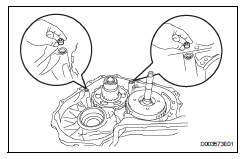
- Install 2 new overdrive brake gaskets.
- Install differential gear assembly

- Install the differential gear to the transaxle.
- Install no. 2 Thrust bearing underdrive race

- Install the thrust bearing race to the underdrive planetary gear.
- Install thrust needle roller bearing

- Calculate the end play value using the following formula and values of dimensions d and e that were measured when installing cylindrical roller bearing and underdrive planetary gear. Select an appropriate underdrive planetary gear thrust bearing race no. 2 Which satisfies the specified end play value, and instal it.
End play: 0.498 To 0.993 Mm (0.0196 To 0.0390 In.)
Hint:
End play = dimension e - dimension d - thrust bearing thickness 3.28Mm (0.1291 In.) - Underdrive thrust bearing race thickness.
Standard race thickness 
Standard bearing and bearing race diameter

- Install oil pump assembly

- Install the oil pump to the transaxle with the 7 bolts.
Torque: 22 n*m (224 kgf*cm, 16 ft.*Lbf)

- Coat the o-ring of the oil pump with atf.
- Install transaxle housing

- Remove any packing material and be careful not to get oil on the contacting surface of the transaxle housing.
- Apply fipg to the transaxle.
Seal packing: toyota genuine seal packing 1281,
Three bond 1281 or equivalent

- Install the transaxle housing to the transaxle with the 16 bolts.
Torque: 22 n*m (224 kgf*cm, 16 ft.*Lbf) for bolt a
29 N*m (296 kgf*cm, 21 ft.*Lbf) for bolt b and c
Hint:
Each bolt length is indicated below.
Bolt length:
50 Mm (1.969 In.) For bolt a
50 Mm (1.969 In.) For bolt b
42 Mm (1.654 In.) For bolt c
Notice:
Because the bolt labeled a are seal bolts, apply seal packing to new bolts and tighten them within 10 minutes after application.
Seal packing: toyota genuine seal packing 1281,
Three bond 1281 or equivalent
- Install no. 1 Transaxle case plug

- Install 2 new o-rings to the 2 plugs.
- Install the 2 plugs to the transaxle housing.
Torque: 7.4 N*m (75 kgf*cm, 65 in.*Lbf)
- Inspect input shaft end play (see page ax- 184)
- Fix automatic transaxle assembly

- Install manual valve lever shaft oil seal

- Coat a new oil seal with atf.
- Install the oil seal to the transaxle.
- Install parking lock rod sub-assembly

- Install manual valve lever sub-assem

- Install a new spacer and manual valve lever shaft to the transaxle.

- Using a pin punch and hammer, tap in a new pin.

- Turn the spacer and lever shaft to align the small hole for locating the staking position mark on the lever shaft.
- Using a pin punch, stake the spacer through the small hole.
- Check that the spacer does not turn.
- Install manual valve lever shaft retainer spring

- Using needle-nose pliers, install the retainer spring.
- Install parking lock pawl bracket
- Install the parking lock pawl bracket with the 2 bolts.

Torque: 20 n*m (205 kgf*cm, 15 ft.*Lbf) bolt length: 25 mm (0.984 In.)
- Install manual detent spring subassembly

- Install the manual detent spring with the 2 bolts.
Notice:
Make sure to install the manual detent spring and cover in this order.
Torque: 20 n*m (204 kgf*cm, 16 ft.*Lbf) for bolt a 12 n*m (122 kgf*cm, 9 ft.*Lbf) for bolt b
Hint:
Each bolt length is indicated below.
27 Mm (1.063 In.) For bolt a
16 Mm (0.630 In.) For bolt b
- Install b-3 accumulator piston
- Coat a new o-ring with atf, and install it to the b-3 accumulator piston.

- Coat the piston with atf, install it to the transaxle.

Standard accumulator spring 
- Install c-1 accumulator piston

- Coat 2 new o-rings with atf, and install them to the c-1 accumulator piston.
- Coat the piston with atf, and install it to the transaxle.

Standard accumulator spring 
- Install c-3 accumulator piston

- Coat a new o-ring with atf, and install it to the c-3 accumulator piston.

- Coat the piston with atf, install it to the transaxle case.
Standard accumulator spring 
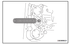
- Install the spring from the c-3 accumulator piston.
- Install check ball body

- Install the check ball body and spring.
- Install brake drum gasket

- Coat a new brake drum gasket with atf, and install it to the transaxle.
- Install transaxle case 2nd brake gasket

- Coat a new transaxle case 2nd brake gasket with atf, and install it to the transaxle.
- Install no. 1 Governor apply gasket

- Coat a new governor apply gasket no. 1 With atf, and install it to the transaxle.
- Install transmission wire

- Coat a new o-ring with atf, and install it to the transaxle solenoid wire.

- Install the solenoid wire retaining bolt torque: 5.4 N*m (55 kgf*cm, 48 in.*Lbf)
- Install transmission valve body assembly

- Align the groove of the manual valve with the pin of lever.
- Install the 17 bolts.
Torque: 11 n*m (112 kgf*cm, 8 ft.*Lbf)
Notice:
- Push the valve body against the accumulator piston spring and the check ball body to install it.
- Tighten the bolts marked by * in the illustration first temporarily because they are positioning bolts.
Hint:
Each bolt length is indicated below.
Bolt length:
25 Mm (0.984 In.) For bolt a
41 Mm (1.614 In.) For bolt b
45 Mm (1.771 In.) For bolt c
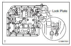
- Connect the 5 solenoid connectors.
- Coat the o-ring of the temperature sensor with atf.
- Install the atf temperature sensor with the lock plate and bolt.
Torque: 6.6 N*m (67 kgf*cm, 58 in.*Lbf)
- Install valve body oil strainer assembly

- Coat a new o-ring with atf.
- Install the o-ring to the oil strainer.

- Install the oil strainer with the 3 bolts.
Torque: 11 n*m (112 kgf*cm, 8 ft.*Lbf)
- Install automatic transaxle oil pan subassembly

- Install the 3 magnets in the oil pan.
- Install a new oil pan gasket to the oil pan.

- Install the oil pan to the transaxle with the 18 bolts.
Torque: 7.6 N*m (77 kgf*cm, 67 in.*Lbf)
Notice:
Because the bolts are seal bolts, apply seal packing to new bolts and tighten them within 10 minutes after application.
- Install no. 1 Transaxle case plug

- Coat 4 new o-rings with atf, and install them to the 4 plugs.
- Install the 4 plugs to the transaxle case.
Torque: 7.4 N*m (75 kgf*cm, 65 in.*Lbf)
- Install speed sensor

- Coat 2 new o-rings with atf, and install them to the 2 sensors.
- Install the 2 sensors with the 2 bolts.
Torque: 11 n*m (112 kgf*cm, 8 ft.*Lbf)
- Install oil cooler inlet tube union

- Coat a new o-ring with atf, and install it to the union.
- Install the union to the transaxle.
Torque: 27 n*m (276 kgf*cm, 20 ft.*Lbf)
- Install oil cooler outlet tube union

- Coat a new o-ring with atf, and install it to the union.
- Install the union to the transaxle.
Torque: 25 n*m (255 kgf*cm, 18 ft.*Lbf)
- Install breather plug hose
- Install park/neutral position switch assembly

- Install the park/neutral position switch to the manual valve shaft.
- Temporarily install the 2 bolts
- Install a new lock plate and tighten the manual valve shaft nut.
Torque: 5.4 N*m (55 kgf*cm, 48 in.*Lbf)

- Temporarily install the control shaft lever.

- turn the lever counterclockwise until it stops, and then turn it clockwise 2 notches.
- Remove the control shaft lever.

- Align the groove with neutral basic line.
- Hold the switch in this position and tighten the 2
bolts.
Torque: 6.9 N*m (70 kgf*cm, 61 in.*Lbf)

- Using a screwdriver, stake the nut with the lock plate.

- Install the control shaft lever with the washer and
nut.
Torque: 13 n*m (133 kgf*cm, 10 ft.*Lbf)
 Inspection
Inspect automatic transaxle oil panel
sub-assembly
Remove the magnets and use them to collect any
steel chips. Examine the chips and particles in the
pan and on the magnet to determ ...
 Oil pump
Components
...
Other materials:
Evaporative emission control system leak detected
Dtc summary
Description
The description can be found in the evap (evaporative emission) system (see
page es-335).
Inspection procedure
Refer to the evap system (see page es-340).
Monitor description
5 Hours* after the ignition switch is turned off, the leak detection pump
creates n ...
Brake pedal
Components
Removal
Disconnect cable from negative battery
terminal
Caution:
Wait at least 90 seconds after disconnecting the
cable from the negative (-) battery terminal to
prevent airbag and seat belt pretensioner activation.
Remove instrument panel sub-assembly
Remov ...
Inspection
Inspect camshaft timing oil control valve
assembly
Measure the resistance of the oil control valve.
Standard resistance
If the result is not as specified, replace the oil control
valve assembly.
Check the operation.
Apply battery voltage across the terminals and
chec ...
