Toyota RAV4 (XA40) 2013-2018 Service Manual: Rear no. 1 Suspension arm
Components

Removal
Hint:
- Use the same procedures for the rh side and lh side.
- The procedures listed below are for the lh side.
- Remove rear wheel
- Remove rear no. 1 Suspension arm assembly lh

- Support the no. 2 Suspension arm lh.

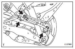
- Remove the bolt and 2 nuts from the suspension member and axle carrier.
Hint:
While fixing the nut in place, loosen and remove the bolt from the suspension member side.
- Using sst, disconnect the suspension arm from the axle carrier.
Sst 09610-20012
Notice:
Do not damage the dust cover.
Inspection
- Inspect rear no. 1 Suspension arm assembly lh

- As shown in the illustration, move the ball joint stud back and forth 5 times before installing the nut.
- Using a torque wrench, turn the nut continuously at a rate of 2 to 4 seconds per turn and take the torque reading on the fifth turn.
Standard turning torque: 3.4 N*m (35 kgf*cm, 30 in.*Lbf)
- Check for any cracks and grease leaks on the ball joint dust cover.
Installation
Hint:
- Use the same procedures for the rh side and lh side.
- The procedures listed below are for the lh side.
- Temporarily tighten rear no. 1 Suspension arm assembly lh
- Temporarily install the suspension arm with the bolt and 2 nuts to the suspension member and axle carrier.
- Install rear wheel
- Install the wheel.
Torque: 103 n*m (1,050 kgf*cm, 76 ft.*Lbf)
- Tighten rear no. 1 Suspension arm assembly lh
- Install the nut and 2 bolts.
Torque: 90 n*m (918 kgf*cm, 66 ft.*Lbf) for bolt 100 n*m (1,020 kgf*cm, 74 ft.*Lbf) for nut
Notice:
For the nut on the rear suspension member side, do not tighten the nut.
- Inspect and adjust rear wheel alignment
- Inspect and adjust the rear wheel alignment (see page sp-7).
 Rear upper control arm
Components
Removal
Hint:
Use the same procedures for the rh side and lh side.
The procedures listed below are for the lh side.
Remove rear wheel
Disconnect skid control sensor wire ...
 Rear no. 2 Suspension arm
Components
Removal
Hint:
Use the same procedures for the rh side and lh side.
The procedures listed below are for the lh side.
Remove rear wheel
Disconnect no. 2 Parking brake cabl ...
Other materials:
Problem symptoms table
Hint:
Use the table below to help determine the cause of the
problem symptom. The potential causes of the symptoms
are listed in order of probability in the "suspected area"
column of the table. Check each symptom by checking the
suspected areas in the order they are listed. Re ...
Only rear door lh lock / unlock functions do not operate
Description
The main body ecu receives lock / unlock switch signals and activates the
door lock motor accordingly.
Wiring diagram
Inspection procedure
Inspect rear door with motor lock assembly lh
Apply the battery voltage to the door lock motor and
check the operation of th ...
Check for open circuit
For an open circuit in the wire harness in fig. 1,
Check the resistance or voltage, as described below.
Check the resistance.
Disconnect connectors a and c, and measure
the resistance between them.
Standard resistance (fig. 2)
Hint:
Measure the resistance while lightly s ...
