Toyota RAV4 (XA40) 2013-2018 Service Manual: Radiator
Components
On-vehicle inspection
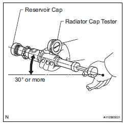
- Check radiator reservoir cap subassembly
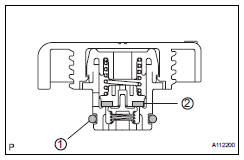
- Measure the valve opening pressure.
- If there are water stains or foreign matter on oring 1, clean it with water and finger scouring.
- Check that o-ring 1 is not deformed, cracked or swollen.
- Apply engine coolant to o-ring 1 and rubber packing 2 before using a radiator cap tester.
- When using the cap tester, tilt it more than 30 degrees.
- Pump the cap tester several times, and check the maximum pressure*.
Pump speed: 1 pump per second
*: Even if the cap cannot maintain the maximum pressure, it is not a defect.
Judgment criterion 
If the maximum pressure is less than the minimum standard value, replace the radiator reservoir cap sub-assembly.
On-vehicle cleaning
- Inspect radiator assembly
- Check that the radiator and condenser are not blocked with leaves, dirt, or insects. Clean the hose connections.
If the fins are blocked, wash them with water or a steam cleaner.
Notice:
- If the distance between the steam cleaner and core is too close, the fins may be damaged.
- Keep the following injection distance.
Standard injection distance 
- If the fins are bent, straighten them with a screwdriver or pliers.
- Never apply water directly onto the electronic components.
- Dry the fins with compressed air.
Removal
- Disconnect cable from negative battery terminal
Caution:
Wait at least 90 seconds after disconnecting the cable from the negative (-) battery terminal to prevent airbag and seat belt pretensioner activation.
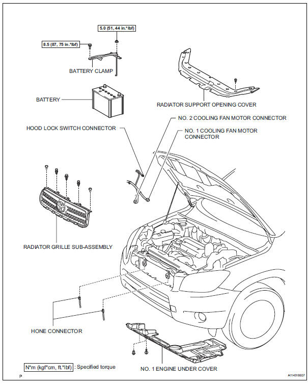
- Remove radiator support opening cover
- Remove battery clamp
- Remove the bolt, nut and clamp.
- Remove battery
- Remove no. 1 Engine under cover
- Drain engine coolant (see page co-6)
- Remove radiator grille sub-assembly (see page et-6)
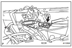
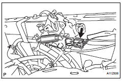
- Disconnect hood lock switch connector
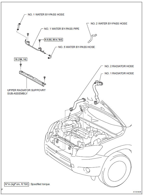
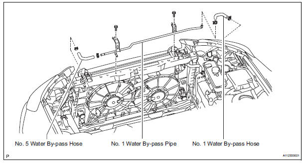
- Disconnect no. 1 Water by-pass hose
- Disconnect the hose from the radiator reservoir.
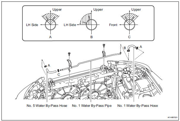
- Disconnect no. 5 Water by-pass hose
- Disconnect the hose from the radiator.
- Remove no. 1 Water by-pass pipe
- Disconnect the pipe from the no. 1 Radiator hose.
- Remove the 2 bolts and the pipe.
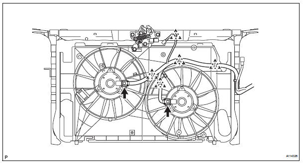
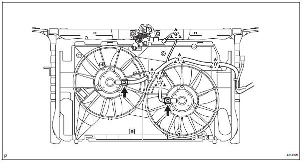
- Disconnect cooling fan motor harness
- Disconnect the 2 fan motor connectors from the 2 fan motors.
- Detach the 5 harness clamps from the fan shroud and upper radiator support.
- Disconnect horn connector
- Disconnect the 2 horn connectors.
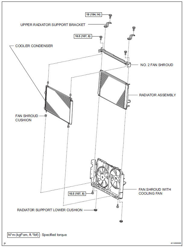
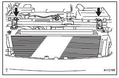
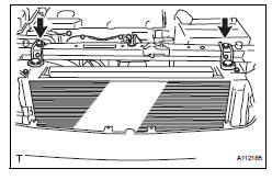
- Remove upper radiator support bracket
- Remove the 2 bolts and the 2 upper radiator support brackets.
- Remove no. 2 Fan shroud
- Remove the 2 bolts.
- Detach the 2 claws and no. 2 Shroud.
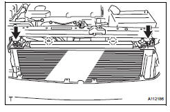
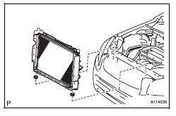
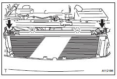
- Remove upper radiator support subassembly
- Remove the 4 bolts and upper radiator support with hood lock.
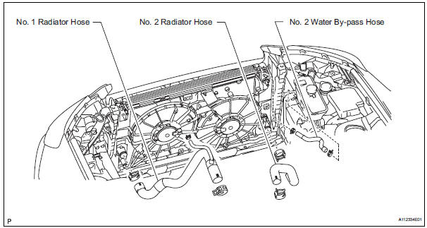
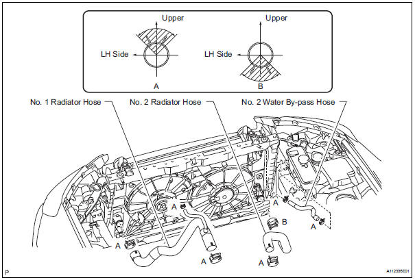
- Disconnect no. 1 Radiator hose
- Disconnect no. 2 Radiator hose
- Disconnect no. 2 Water by-pass hose
Disconnect the by-pass hose from the radiator reservoir and radiator.
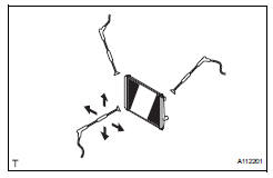
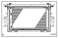
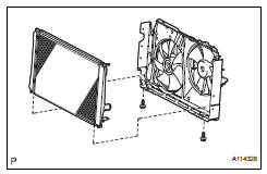
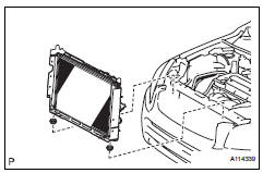
- Remove radiator assembly
- Separate the cooler condenser from the radiator.
Hint:
After detaching the condenser, make sure that all 4 fan shroud cushions are present
- Remove the radiator with the 2 radiator support lowers.
Hint:
After detaching the radiator, make sure that both radiator support lowers are present.
- Remove fan shroud with cooling fan
- Remove the 2 bolts and radiator from the fan shroud.
Installation
- Install fan shroud with cooling fan
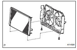
- Install the fan shroud with cooling fan with the 2 bolts to the radiator.
Torque: 10.5 N*m (107 kgf*cm, 8 ft.*Lbf)
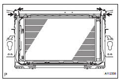
- Install radiator assembly
- Install the 4 fan shroud cushions to the cooler condenser.
- Set the cooler condenser to the fan shroud.
- Install the 2 radiator support lower cushions to the fan shroud.
- Install the radiator with cooler condenser and fan shroud to the radiator support lower.
- Install upper radiator support subassembly
- Install the upper radiator support with the 4 bolts.
Torque: 19 n*m (194 kgf*cm, 14 ft.*Lbf)
- Install no. 2 Fan shroud
- Attach the 2 claws to install the no. 2 Fan shroud and install the 2 bolts.
Torque: 10.5 N*m (107 kgf*cm, 8 ft.*Lbf)
- Install upper radiator support bracket
- Install the bracket with the 2 bolts.
Torque: 19 n*m (194 kgf*cm, 14 ft.*Lbf)
- Connect horn connector
- Connect the 2 horn connectors.
- Connect no. 2 Water by-pass hose
- Connect the by-pass hose to the radiator and radiator reservoir.
Hint:
The direction of the hose clamp is indicated in the illustration.
- Connect no. 2 Radiator hose
Hint:
The direction of the hose clamp is indicated in the illustration.
- Connect no. 1 Radiator hose
Hint:
The direction of the hose clamp is indicated in the illustration.
- Connect cooling fan motor harness
- Attach the harness with the 5 clamps.
- Connect the 2 fan motor connectors.
- Install no. 1 Water by-pass pipe
- Install the by-pass pipe with the 2 bolts to the upper radiator support.
Torque: 9.0 N*m (92 kgf*cm, 80 in.*Lbf)
- Connect the no. 1 Radiator hose to the pipe.
Hint:
The direction of the hose clamp is indicated in the lustration.
- Connect no. 5 Water by-pass hose
- Connect the by-pass hose to the radiator.
Hint:
The direction of the hose clamp is indicated in the lustration.
- Connect no. 1 Water by-pass hose
- Connect the by-pass hose to the radiator and radiator reservoir.
Hint:
The direction of the hose clamp is indicated in the illustration.
- Connect hood lock switch connector
- Install radiator grille sub-assembly (see page et-10)
- Install battery
- Install battery clamp
- Attach the hook of the battery clamp to the battery bracket.
- Temporarily tighten the nut and install the bolt.
- Adjust the battery clamp's position.
- Fully tighten the bolt and nut.
Torque: 8.5 N*m (87 kgf*cm, 75 in.*Lbf) for bolt 5.0 N*m (51 kgf*cm, 44 in.*Lbf) for nut
- Connect cable to negative battery terminal
- Add engine coolant (see page co-6)
- Check for engine coolant leaks (see page co-1)
- Install radiator support opening cover
 Cooling fan relay
On-vehicle inspection
Disconnect cable from negative battery
terminal
Caution:
Wait at least 90 seconds after disconnecting the
cable from the negative (-) battery terminal to
prevent airb ...

Other materials:
Power outlet socket
Components
Removal
Disconnect cable from negative battery
terminal
Caution:
Wait at least 90 seconds after disconnecting the
cable from the negative (-) battery terminal to
prevent airbag and seat belt pretensioner activation.
Remove switch base (see page ip-21)
Remove power o ...
Rear seats
Adjustment procedure
Pull up the lever. Then lean back to the desired angle and release the
lever.
When a person sits in the rear center position, align all seatbacks at the
same angle.
Folding down the rear seatbacks
Before folding down the rear seatbacks
Stow the rear center seat bel ...
Adjusting the mirrors
Make sure that you can see backward clearly by adjusting the inside
and outside rear view mirrors properly.
Caution
Observe the following precautions.
Failure to do so may result in death or serious injury.
Do not adjust the position of the driver’s seat while driving.
Doing so could ...
