Toyota RAV4 (XA40) 2013-2018 Service Manual: On-vehicle inspection
Notice:
- Perform the maf meter inspection according to the procedures below.
- Only replace the maf meter when both the long ft#1 value and maf value in the data list (with the engine stopped) are not within the normal operating range.
- Inspect mass air flow meter
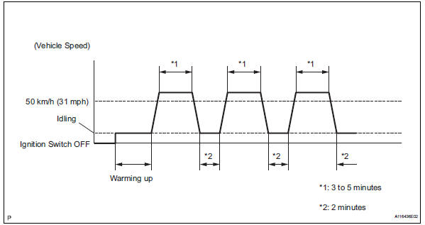
- Perform confirmation driving pattern.
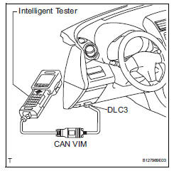
- Connect the intelligent tester to the dlc3.
- Turn the ignition switch on.
- Turn the tester on.
- Clear the dtcs (see page es-35).
- Start the engine and warm it up with all accessory switches off until the engine coolant temperature is 75°c (167°f) or more.
- Drive the vehicle at 50 km/h (31 mph) or more for 3 to 5 minutes*1.
- Allow the engine to idle for 2 minutes*2.
- Perform steps *1 and *2 at least 3 times.
- Read the value using the intelligent tester (long ft#1).
- Select the following menu items: diagnosis / enhanced obd ii / data list / primary / long ft#1.
- Read the values displayed on the tester.
Standard value: within -15 to +15%
If the result is not within the specified range, perform the inspection below.
- Read the value using the intelligent tester (maf).
Notice:
- Turn off the engine.
- Perform the inspection with the vehicle indoors and on a level surface.
- Perform the inspection of the maf meter while it is installed to the air cleaner case (installed to the vehicle).
- During the test, do not use the exhaust air duct to perform suction on the exhaust pipe.
- Turn the ignition switch to acc.
- Turn the ignition switch on (do not run the engine).
- Turn the tester on.
- Select the following menu items: diagnosis / enhanced obd ii / data list / primary / maf.
- Wait 30 seconds, and read the values on the intelligent tester.
Standard condition: less than 0.45 G/sec.
- If the result is not as specified, replace the maf meter.
- If the result is within the specified range, inspect the cause of the extremely rich or lean air-fuel ratio (see page es-147).
 Mass air flow meter
Components
...
 Removal
Disconnect cable from negative battery terminal
Caution:
Wait at least 90 seconds after disconnecting the
cable from the negative (-) battery terminal to
prevent airbag and seat belt pretensi ...
Other materials:
If your vehicle has to be stopped in an emergency
Only in an emergency, such
as if it becomes impossible
to stop the vehicle in the
normal way, stop the vehicle
using the following procedure:
Stopping the vehicle
1. Steadily step on the brake
pedal with both feet and
firmly depress it.
Do not pump the brake pedal
repeatedly as this will increase t ...
System description
General
The air conditioning system has the following
features:
In accordance with the temperature set using the
temperature control switch, the air conditioning
amplifier determines the outlet temperature
based on the input signals from various sensors.
In addition, corre ...
Adjusting the mirrors
Make sure that you can see backward clearly by adjusting the inside
and outside rear view mirrors properly.
Caution
Observe the following precautions.
Failure to do so may result in death or serious injury.
Do not adjust the position of the driver’s seat while driving.
Doing so could ...
