Toyota RAV4 (XA40) 2013-2018 Service Manual: Oil pump
Components


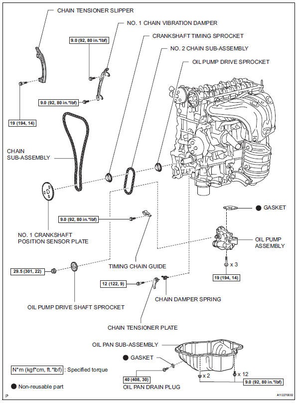

Removal
- Remove chain sub-assembly
- Remove the chain (see page em-22).
- Remove oil pump assembly

- Remove the 3 bolts, oil pump and gasket.
Disassembly
- Remove oil pump strainer

- Remove the 2 nuts, oil pump strainer and gasket.
- Remove oil pump relief valve

- Using a 27 mm socket wrench, remove the plug.
- Remove the valve spring and relief valve.
- Remove oil pump cover

- Remove the 5 bolts and oil pump cover.
Inspection
- Inspect oil jet

- Check the oil jet for damage or clogging.
If necessary, repair the cylinder block.
- Inspect oil pump relief valve

- Check the relief valve.
- Coat the valve with engine oil, and then check
that the valve falls smoothly into the valve hole
by its own weight.
If it does not, replace the relief valve. If necessary, replace the oil pump assembly.
- Inspect oil pump rotor

- Check the side clearance.
- Using a feeler gauge and precision straightedge, measure the clearance between the rotors and precision straightedge.
Standard clearance: 0.030 To 0.085 Mm (0.0012 To 0.0033 In.)
Maximum clearance: 0.16 Mm (0.0063 In.)
If the side clearance is greater than the maximum, replace the oil pump assembly.
- Check the tip clearance.

- Using a feeler gauge, measure the clearance between the drive and driven rotor tips.
Standard clearance: 0.080 To 0.160 Mm (0.0031 To 0.0063 In.)
Maximum clearance: 0.35 Mm (0.0138 In.)
If the tip clearance is greater than the maximum, replace the oil pump assembly.
- Check the body clearance.
- Using a feeler gauge, measure the clearance between the driven rotor and pump body.

Standard clearance: 0.100 To 0.170 Mm (0.0039 To 0.0067 In.)
Maximum clearance: 0.325 Mm (0.01128 In.)
If the body clearance is greater than the maximum, replace the oil pump assembly.
- Inspect oil pump drive chain and 2 oil pump sprockets

- Using vernier calipers, measure the length of the 8 links with the chain fully stretched.
Maximum chain elongation: 52.4 Mm (2.063 In.)
If the elongation is greater than the maximum, replace the chain.
Hint:
Make the measurements at 3 or more places selected at random.
- Wrap the chain around the oil pump sprocket.
- Using vernier calipers, measure the sprocket diameter with the chain.
Notice:
Vernier calipers must contact the chain rollers when measuring.
Minimum sprocket diameter (with chain): crankshaft 48.2 Mm (1.898 In.) Oil pump drive shaft 48.2 Mm (1.898 In.)
If the diameter is less than the minimum, replace the chain and sprockets.

- Inspect chain tensioner plate
- Measure the chain tensioner plate wear.
Maximum wear: 0.5 Mm (0.020 In.)

If the wear is greater than the maximum, replace the chain tensioner plate.
Reassembly
- Install oil pump rotor
- Coat the drive rotor and driven rotor with engine oil.
- Place the drive and driven rotors into the oil pump with the marks facing the pump cover side.

- Install oil pump cover

- Install the oil pump cover with the 5 bolts.
Torque: 8.8 N*m (90 kgf*cm, 78 in.*Lbf)
- Install oil pump relief valve

- Coat the relief valve with engine oil.
- Insert the relief valve and spring into the pump body hole.
- Using a 27 mm socket wrench, install the plug.
Torque: 49 n*m (500 kgf*cm, 36 ft.*Lbf)
- Install oil pump strainer

- Install a new gasket and the oil strainer with the 2 nuts.
Torque: 8.8 N*m (90 kgf*cm, 78 in.*Lbf)
Installation
- Install oil pump assembly
- Install a new gasket and the oil pump with the 3 bolts.
Torque: 19 n*m (194 kgf*cm, 14 ft.*Lbf)

- Install chain sub-assembly
- Install the chain (see page em-32).
 Oil filter
Components
Replacement
Caution:
Prolonged and repeated contact with engine oil will
cause the loss of natural oils from the skin, leading to
dryness, irritation and dermatitis. In additi ...
 Brake
Brake
...
Other materials:
Idle control system malfunction
Description
The idling speed is controlled by the etcs (electronic throttle control
system). The etcs is comprised
of: 1) the one valve type throttle body; 2) the throttle actuator, which
operates the throttle valve; 3) the
throttle position (tp) sensor, which detects the opening angle of ...
Parking brake
Sets the parking brake
Fully pull the parking brake while
depressing the brake pedal.
Releases the parking brake
Slightly raise the lever and lower it
completely while pressing the button.
Usage in winter time
Notice
Before driving
Fully release the parking brake.
Driving t ...
Installation
Install no. 2 Radiator grille lower
Install the radiator grille and attach the 16 claws.
Install no. 1 Radiator grille lower
Install the radiator grille and attach the 16 claws.
Install radiator grille
Install the radiator grille with the 6 claws.
...
