Toyota RAV4 (XA40) 2013-2018 Service Manual: Downhill assist control operation switch (test mode dtc)

Description
The downhill assist control switch is connected to the skid control ecu in the abs and traction actuator.
Dtc c1379/74 can be detected when the downhill assist control switch sends the downhill assist control switch signal or test mode ends. Dtc c1379/74 is output only in test mode.
![]()
Wiring diagram
Refer to downhill assist control switch circuit (see page bc-157).
Inspection procedure
Notice:
When replacing the abs and traction actuator, perform zero point calibration (see page bc-24).
- Check wire harness (skid control ecu - body ground)
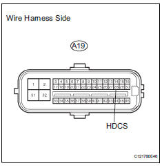
- Disconnect the a19 ecu.
- Measure the resistance of the wire harness side connector.
Standard resistance 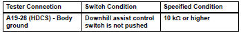


- Inspect downhill assist control switch
- Remove the downhill assist control switch.
- Measure the resistance of the switch.
Standard resistance 


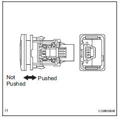
- Check wire harness (skid control ecu - downhill assist control switch)
- Disconnect the a19 ecu connector.
- Disconnect the e31 switch connector.
- Measure the resistance of the wire harness side connectors.
Standard resistance 


Replace abs and traction actuator assembly
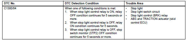
Stop light control relay malfunction
![]()
Description
The skid control ecu inputs the stop light switch signal and detects the status of the brake operation.
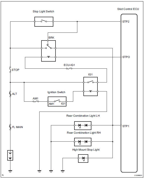
Wiring diagram
Inspection procedure
Notice:
When replacing the abs and traction actuator, perform zero point calibration (see page bc-24).
- Check stop light (operation)
- Check that the light illuminates when the brake pedal is depressed, and turns off when the brake pedal is released.
Ok 


- Check wire harness (skid control ecu - battery)
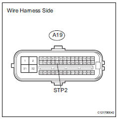
- Disconnect the a19 ecu connector.
- Measure the voltage of the wire harness side connector.
Standard voltage 


- Check wire harness (skid control ecu)
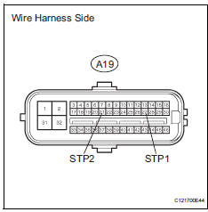
- Disconnect the a19 ecu connector.
- Measure the resistance of the wire harness side connector
Standard resistance 

- Perform active test by intelligent tester (stop light relay)
- Select the active test, generate a control command, and then check that the stop light relay operates.

Ok: the stop lights illuminate or turn off.


- Reconfirm dtc
- Clear the dtc (see page bc-47).
- Start the engine.
- Drive the vehicle at a speed of 5 km/h (3 mph) or more for several seconds.
- Check if the same dtc is output (see page bc-47).
Result 


Replace abs and traction actuator assembly
- Inspect stop light control relay (marking: brk)
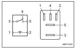
- Remove the stop light control relay from the engine room no. 1 Relay block.
- Measure the resistance of the relay.
Standard resistance 


- Check wire harness (engine room no. 1 Relay block - skid control ecu and battery)
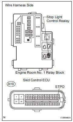
- Remove the stop light control relay.
- Disconnect the a19 ecu connector.
- Measure the voltage of the wire harness side connector.
Standard voltage 
- Measure the resistance of the wire harness side connector.
Standard resistance 


- Reconfirm dtc
- Clear the dtc (see page bc-47).
- Start the engine.
- Drive the vehicle at a speed of 5 km/h (3 mph) or more for several seconds.
- Check if the same dtc is output (see page bc-47).
Result 


Replace abs and traction actuator assembly
- Check wire harness (stop light switch - battery)
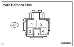
- Disconnect the a3 switch connector.
- Measure the voltage of the wire harness side connector.
Standard voltage 


- Inspect stop light switch assembly
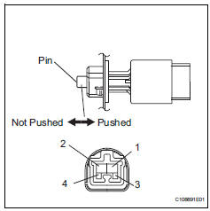
- Remove the stop light switch connector.
- Measure the resistance of the switch.
Standard resistance 


- Check wire harness (stop light switch - stop light control relay)
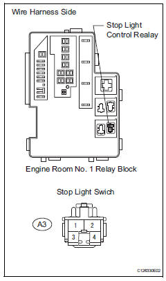
- Disconnect the a3 switch connector.
- Remove the stop light control relay.
- Measure the resistance of the wire harness side connectors.
Standard resistance 


- Inspect stop light control relay (marking: brk)
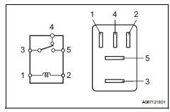
- Remove the stop light control relay from the engine room no. 1 Relay block.
- Measure the resistance of the relay.
Standard resistance 


- Check wire harness (stop light and rear combination light - control relay)
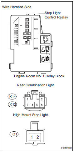
- Disconnect the q1, k12 and k14 light connectors.
- Remove the stop light control relay.
- Measure the resistance of the wire harness side connectors.
Standard resistance 


Check for intermittent problems
 Different diameter tire malfunction
Description
The skid control ecu measures the speed of each wheel by receiving signals
from the speed sensor.
These signals are used for recognizing that all 4 wheels are operating properly. ...
 Control module communication bus off
Description
Inspection procedure
The skid control ecu inputs the signals from the ecm, steering angle sensor,
and yaw rate and
acceleration sensor via can communication system.
Ch ...
Other materials:
How to proceed with troubleshooting
Hint:
*: Use the intelligent tester.
Hint:
If the display indicates a communication fault in the tester,
inspect the dlc3.
Hint:
Record or print dtcs and freeze frame data, if necessary.
Hint:
If the engine does not start, first perform the "check dtc"
procedures a ...
Disassembly (2006/01- )
Remove front axle inboard joint boot no. 2
Clamp
One touch type:
using a screwdriver, remove the no. 2 Inboard joint
boot clamp, as shown in the illustration.
Claw engagement type:
using needle-nose pliers, remove the no. 2 Inboard
joint boot clamp, as shown in the illustra ...
Terminals of ecu
Check power steering ecu
Hint:
Measurements cannot be performed on the c connector
side of the power steering ecu.
Measure the voltage and resistance of the
connectors.
If the result is not as specified, the ecu may have a
malfunction. ...
