Toyota RAV4 (XA40) 2013-2018 Service Manual: Can communication system
Precaution
- Precaution
- Turn the ignition switch off before measuring the resistance of the main wire and the branch wire.
- After the ignition switch is turned off, check that the key reminder warning system and light reminder warning system are not in operation.
- Before measuring the resistance, leave the vehicle for at least 1 minute and do not operate the ignition switch, any switches or doors. If doors need to be opened in order to check connectors, open the doors and leave them open.
Hint:
Operating the ignition switch, any switches or any doors triggers related ecu and sensor communication with the can, which causes resistance variation.
- Steering system handling precautions
- Care must be taken when replacing parts. Incorrect replacement could affect the performance of the steering system and result in hazards when driving.
- Srs airbag system handling precautions
- This vehicle is equipped with an srs (supplemental restraint system) such as the driver airbag and front passenger airbag. Failure to carry out service operations in the correct sequence could cause unexpected srs deployment during servicing and may lead to a serious accident. Before servicing (including installation/removal, inspection and replacement of parts), be sure to read the precautionary notice for the supplemental restraint system (see page rs-1).
- Bus line repair

- After repairing the bus line with solder, wrap the repaired part with vinyl tape (see page in-37).
Notice:
- The canl bus line and canh bus line must be installed together.
- When installing, twist them together.
- Can bus lines are likely to be influenced by noise if the bus lines are not twist together.
- The difference in length between the canl bus line and canh bus line should be less than 100 mm (3.937 In.).
- Leave approximately 80 mm (3.150 In.) Loose in the twisted wires around the connectors.
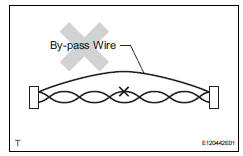
- Do not use bypass wiring between the connectors.
Notice:
The feature of the twisted wire harness will be lost if bypass wiring is used.
- Connector handling

- When inserting tester probes into a connector, insert them from the rear of the connector.

- Use a repair wire to check the connector if it is impossible to check resistance from the rear of the connector.

 Parts location
System diagram
Hint:
The abs and traction actuator (skid control ecu)
detects and stores steering sensor and yaw rate
sensor dtcs and performs dtc communication by
receiving ...
Other materials:
Driving the vehicle
The following procedures
should be observed to
ensure safe driving:
Driving procedure
â– Driving
1. With the brake pedal
depressed, shift the shift
lever to D.
2. Release the parking brake.
If the parking brake is in automatic
mode, the parking brake will be
released automatically.
3. Gradually re ...
Front airbag sensor lh circuit malfunction
Description
The front airbag sensor lh consists of the diagnostic circuit, the frontal
deceleration sensor, etc.
If the center airbag sensor receives signals from the frontal deceleration
sensor, it determines whether or
not the srs should be activated.
Dtc b1615/14 is recorded when a ma ...
Door control transmitter module
Components
Removal
Remove transmitter housing cover
Notice:
Take extra care when handling these precision
electronic components.
Twist the screwdriver in the direction of the arrow
mark in the illustration, and open the transmitter
housing cover.
Notice:
Do not forcibly pry ...
