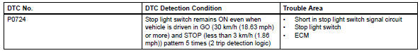
Toyota RAV4 (XA40) 2013-2018 Service Manual: Brake switch "B" circuit high
![]()
Description
The purpose of this circuit is to prevent the engine from stalling while driving in the lock-up condition when the brakes are suddenly applied.
When the brake pedal is depressed, this switch sends a signal to the ecm. Then the ecm cancels the operation of the lock-up clutch while braking is in progress.
Monitor description
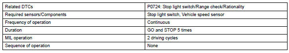
This dtc indicates that the stop light switch remains on. When the stop light switch remains on during go and stop driving, the ecm interprets this as a fault in the stop light switch. Then the mil illuminates and the ecm stores the dtc. The vehicle must go (30 km/h (18.63 Mph) or more) and stop (less than 3 km/h (1.86 Mph)) 5 times for 2 driving cycles in order for the dtc to be output.
Monitor strategy
Typical enabling conditions
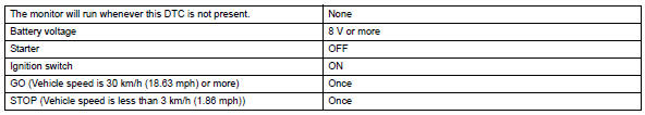
Typical malfunction thresholds
![]()
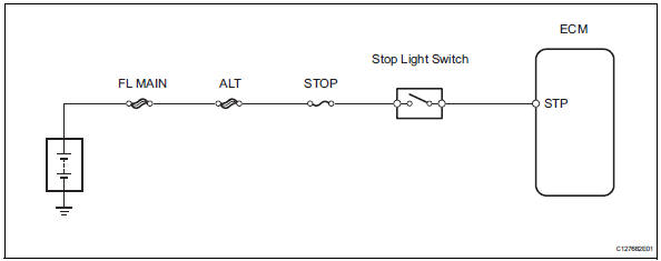
Wiring diagram
Inspection procedure
Hint:
Using the intelligent tester's data list allows switch, sensor, actuator and other item values to be read without removing any parts. Reading the data list early in troubleshooting is one way to save time.
Notice:
In the table below, the values listed under "normal condition" are reference values. Do not depend solely on these reference values when deciding whether a part is faulty or not.
- Warm up the engine.
- Turn the ignition switch off.
- Connect the intelligent tester to the can vim. Then connect the can vim to the dlc3.
- Turn the ignition switch on and turn the tester on.
- Enter the following menus: diagnosis / enhanced obd ii / data list.
- Follow the instructions on the tester and read the data list.
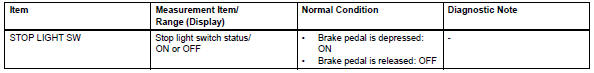
- Inspect stop light switch
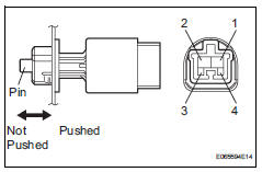
- Remove the a3 stop light switch.
- Measure the resistance of the switch.
Standard resistance 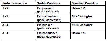


- Check wire harness (ecm - battery)
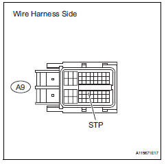
- Measure the voltage of the wire harness side connector.
Standard voltage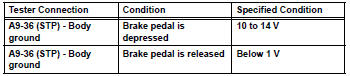

Replace ecm
 Input speed sensor circuit no signal
Description
This sensor detects the rotation speed of the turbine, which shows the input
revolution of the transaxle. By
comparing the input speed signal (nt) with the counter gear speed sens ...
 Torque converter clutch solenoid performance (shift solenoid valve dsl)
Description
The ecm uses the signals from the throttle position sensor, air-flow meter,
turbine (input) speed sensor,
intermediate (counter) shaft speed sensor and crankshaft position sensor t ...
Other materials:
Throttle actuator control motor circuit
Description
The throttle actuator is operated by the ecm and opens and closes the
throttle valve using gears.
The opening angle of the throttle valve is detected by the throttle position (tp)
sensor, which is mounted
on the throttle body. The tp sensor provides feedback to the ecm. This ...
Data list / active test
Hint:
Using the intelligent tester's data list allows switch, sensor,
actuator and other item values to be read without removing
any parts. Reading the data list early in troubleshooting is
one way to save time.
Data list for occupant classification ecu
Connect the intelligent test ...
High pitched horn
Components
Removal
Remove radiator support opening cover
(see page et-4)
Remove front fender liner lh (see page et-4)
Remove front fender liner rh (see page et-4)
Remove front bumper cover (see page et-5)
Remove high pitched horn
Disconnect the horn connector.
Remove t ...
