Toyota RAV4 (XA40) 2013-2018 Service Manual: Brake front brake flexible hose
Components

Removal
Hint:
- Use the same procedures for the lh side and rh side.
- The procedures listed below are for the lh side.
- Remove front wheel
- Drain brake fluid
Notice:
Wash off brake fluid immediately if it comes in contact with any painted surface.
- Remove front flexible hose

- Disconnect the brake tube (labeled a) from the flexible hose with sst while holding the flexible hose with a wrench.
Sst 09023-00101
Notice:
- Do not bend or damage the brake tube.
- Do not allow any foreign matter such as dirt and dust to enter the brake tube from the connecting point.
- Remove the clip (labeled b).
- Remove the 2 bolts (labeled c, d) and then remove the flexible hose clamp (labeled e) from the knuckle.
- Remove the sensor clamp and flexible hose clamp from the flexible hose bracket.

- Remove the union bolt and gasket(s), and then remove the flexible hose from the disc brake cylinder.

Installation
Hint:
- Use the same procedures for the lh side and rh side.
- The procedures listed below are for the lh side.
- Install disc brake cylinder assembly lh

- Apply silicon grease (multemp si-b) on the contact surfaces of the cylinder parts indicated by the arrows.

- Install the cylinder with the 2 bolts.
Torque: 34.3 N*m (350 kgf*cm, 25 ft.*Lbf)
- Connect front flexible hose

Notice:
The gasket and union bolt must be used as a set, as shown in the illustration.

- Connect the flexible hose with new gasket(s) and the union bolt.
Torque: 29.4 N*m (300 kgf*cm, 22 ft.*Lbf)
Hint:
Install the flexible hose lock securely in the lock hole in the cylinder.
- Fill reservoir with brake fluid (see page br- 6)
- Bleed air from brake master cylinder (see page br-7)
- Bleed air from brake line (see page br-7)
- Bleed air from abs and traction actuator assembly (see page br-8)
- Check brake fluid level in reservoir (see page br-6)
- Check for brake fluid leakage
- Install front wheel torque: 103 n*m (1,050 kgf*cm, 76 ft.*Lbf)
Installation
Hint:
- Use the same procedures for the lh side and rh side.
- The procedures listed below are for the lh side.
- Install front flexible hose
Notice:
- The flexible hose has an identification color. Make
sure of the identification color when installing the
flexible hose.

- The gasket and union bolt must be used as a set, as shown in the illustration.

- Connect the flexible hose with new gasket(s) and the union bolt to the disc brake cylinder.

Torque: 29.4 N*m (300 kgf*cm, 22 ft.*Lbf)
Hint:
Install the flexible hose lock securely in the lock hole in the cylinder.
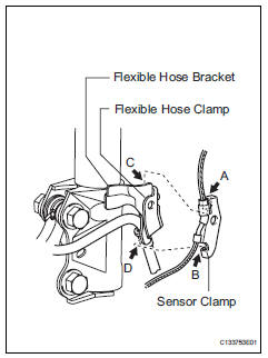
- Set the flexible hose clamp on the flexible hose bracket.
- Simultaneously perform the following: 1) hang the hook part of the sensor clamp (labeled a) on the flexible hose bracket (labeled c); and 2) insert the hook part of the sensor clamp (labeled b) into the flexible hose bracket (labeled d).

- Tighten the bolt (labeled c) to fix the flexible hose
clamp and sensor clamp.
Torque: 18.5 N*m (189 kgf*cm, 14 ft.*Lbf)
- Install the flexible hose with the bolt (labeled d).
Torque: 18.5 N*m (189 kgf*cm, 14 ft.*Lbf)
- Set the flexible hose to the connecting point with the brake tube (labeled a), and then attach a new clip (labeled b).
- Using sst, connect the flexible hose to the brake tube (labeled a) while holding the flexible hose with a wrench.
Sst 09023-00101
Torque: 15.2 N*m (155 kgf*cm, 11 ft.*Lbf) without sst
14 N*m (144 kgf*cm, 10 ft.*Lbf) with sst
Hint:
Use a torque wrench with a fulcrum length of 30 cm (11.81 In.).
Notice:
- Do not bend or damage the brake tube.
- Do not allow any foreign matter such as dirt and dust to enter the brake tube from the connecting point.
- Fill reservoir with brake fluid (see page br- 6)
- Bleed air from brake master cylinder (see page br-7)
- Bleed air from brake line (see page br-7)
- Bleed air from abs and traction actuator assembly (see page br-8)
- Check brake fluid level in reservoir (see page br-6)
- Check for brake fluid leakage
- Install front wheel torque: 103 n*m (1,050 kgf*cm, 76 ft.*Lbf)
 Front brake
Components
Removal
Hint:
Use the same procedures for the lh side and rh side.
The procedures listed below are for the lh side.
Remove front wheel
Drain brake fluid
Notic ...
 Rear brake
Components
Removal
Hint:
Use the same procedures for the lh side and rh side.
The procedures listed below are for the lh side.
Remove rear wheel
Drain brake fluid
Notice:
W ...
Other materials:
Bluetooth® phone
settings
You can adjust the hands-free system to your desired settings.
“Phone/message settings” screen
To display the screen shown below, press the “setup” button, and
select “phone” on the “setup” screen.
Set the phone connection
Setting the sound
Contact/call history settings
...
Fuel information
You must only use unleaded gasoline in your vehicle.
Select octane rating 87 (research octane number 91) or higher.
Use of unleaded gasoline with an octane rating lower than 87
may result in engine knocking. Persistent knocking can lead to
engine damage.
At minimum, the gasoline you use sho ...
Headlight relay circuit
Description
When the light control switch, located on the headlight dimmer switch, is
turned to the head position, the
head relay illuminates the headlights.
Wiring diagram
Inspection procedure
Perform active test by intelligent tester (headlight)
Connect the intelligent tester ( ...
