Toyota RAV4 (XA40) 2013-2018 Service Manual: Transmission control cable assembly
Replacement
- Remove rear console box sub-assembly
- Remove the console box (see page ip-20).
- Disconnect cable from negative battery terminal
Caution:
Wait at least 90 seconds after disconnecting the cable from the negative (-) battery terminal to prevent airbag and seat belt pretensioner activation.
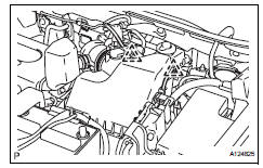
- Remove battery
- Loosen the nut and remove the bolt and battery clamp.
- Remove the battery.
- Remove the battery tray.
- Remove the 4 bolts and battery carrier.
- Remove the 2 bolts and battery bracket reinforcement.
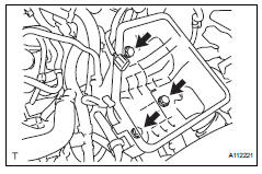
- Remove air cleaner assembly
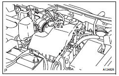
- Disconnect the mass air flow meter connector.
- Remove the 2 clamps of the engine wire.
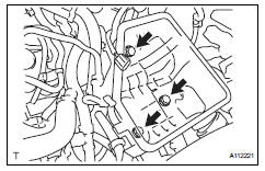
- Remove the 4 bolts from the air cleaner case.
- Disconnect the air cleaner case from the no. 1 Air cleaner inlet.
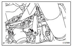
- Remove transaxle control cable assembly
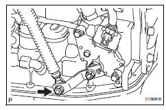
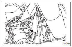
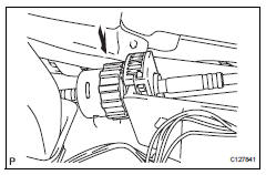
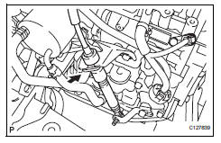
- Remove the nut and disconnect the control cable from the control shaft lever.
- Remove the clip and disconnect the control cable from the control cable bracket.
- Disconnect the control cable from the control cable support.
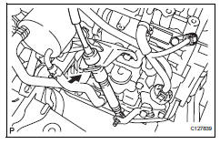
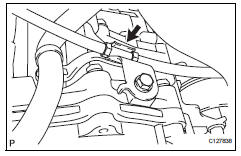
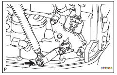
- Remove the bolt and disconnect the clamp of the control cable.
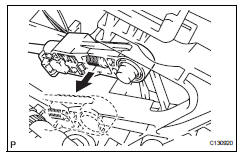
- Disconnect the control cable from the shift lever.
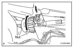
- Turn the nut and disconnect the control cable from the shift lever retainer.
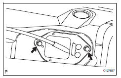
- Remove the 2 bolts and control cable.
- Install transaxle control cable assembly
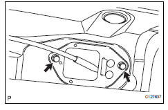
- Install the control cable with the 2 bolts.
Torque: 5.0 N*m (51 kgf*cm, 44 in.*Lbf)
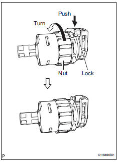
- Turn the nut of the control cable and push in the lock.
- Install the control cable onto the shift lever retainer.
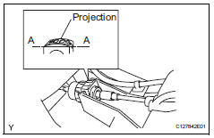
Notice:
- Install the cable with the protruding portion of the cable outer facing upward.
- After installing, check that the lock of the cable outer is protruding beyond portion a-a, as shown in the illustration.
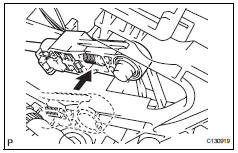
- Connect the control cable to the shift lever.
Notice:
Connect the control cable so that the adjusting mechanism lock of the control cable is installed on the driver side of the vehicle.
- Fix the control cable onto the control cable bracket with the clip.
- Connect the control cable onto the control shaft lever with the nut.
Torque: 12 n*m (122 kgf*cm, 9 ft.*Lbf)
- Connect the clamp of the control cable with the bolt.
Torque: 12 n*m (122 kgf*cm, 9 ft.*Lbf)
- Connect the control cable to the cable support.
- Install air cleaner assembly

- Connect the air cleaner case to the no. 1 Air cleaner inlet.
- Install the air cleaner case with the 4 bolts.
Torque: 5.0 N*m (51 kgf*cm, 44 in.*Lbf)
- Connect the 2 clamps of the engine wire.
- Connect the mass air flow meter connector.
- Install battery
- Install the battery bracket reinforcement with the 2
bolts.
Torque: 20 n*m (204 kgf*cm, 15 ft.*Lbf)
- Install the battery carrier with the 4 bolts.
Torque: 20 n*m (204 kgf*cm, 15 ft.*Lbf)
- Install the battery tray.
- Connect the 2 clamps of the engine wire.
- Install the battery with the battery clamp.
Torque: 8.5 N*m (87 kgf*cm, 75 in.*Lbf) for bolt
5.0 N*m (51 kgf*cm, 44 in.*Lbf) for nut
- Connect cable to negative battery terminal
- Inspect shift lever position
- When shifting the lever from p to the r position with the ignition switch on (ig) and the brake pedal depressed, make sure that the shift lever moves smoothly and moves correctly into position.
- Start the engine and make sure that the vehicle
moves forward when shifting the lever from n to the
d position and moves rearward when shifting the
lever to the r position.
If the operation cannot be performed as specified, inspect the park/neutral position switch and check the shift lever installation condition.
- Adjust shift lever position (see page ax-138)
- Install rear console box sub-assembly
- Install the rear console box (see page ip-26).
 Transmission oil cooler
Components
Removal
Remove transmission oil cooler
*1: Disconnect the no. 3 Water by-pass hose from
the transmission oil cooler.
*2: Disconnect the no. 4 Water by-pass hose from
...
 Floor shift assembly
Components
Removal
Disconnect cable from negative battery
terminal
Caution:
Wait at least 90 seconds after disconnecting the
cable from the negative (-) battery terminal to
preven ...
Other materials:
Diagnosis system
Check dlc3
Check the dlc3:
the power steering ecu uses can (iso11898-1)
and iso9141-2 for communication protocol. The
terminal arrangement of the dlc3 complies with
sae j1962 and matches the iso9141-2 format.
Notice:
*: Before measuring the resistance, leave the
vehicle ...
Hazard warning switch
Components
Removal
Disconnect cable from negative battery
terminal
Caution:
Wait at least 90 seconds after disconnecting the
cable from the negative (-) battery terminal to
prevent airbag and seat belt pretensioner activation.
Remove no. 1 Instrument cluster finish
panel cente ...
Check mode procedure
Hint:
Intelligent tester only:
compared to normal mode, check mode is more sensitive to
malfunctions. Therefore, check mode can detect the
malfunctions that cannot be detected by normal mode.
Notice:
All the stored dtcs and freeze frame data are erased if:
The ecm is changed from normal mo ...
