Toyota RAV4 (XA40) 2013-2018 Service Manual: Solenoid circuit
Description
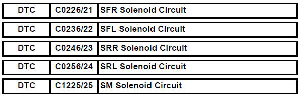
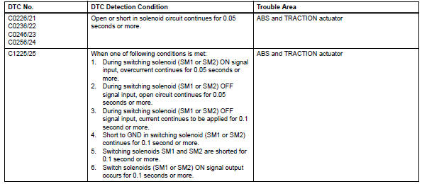
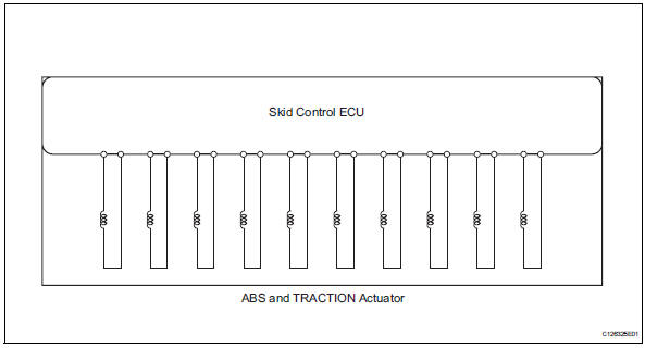
This solenoid is turned on in accordance with signals from the skid control ecu and controls the pressure on the wheel cylinders to control the braking force.
The solenoid and solenoid relay are built into the abs and traction actuator.
Hint:
Dtcs c0226/21, c0236/22, c0246/23, c0256/24 and c1225/25: the skid control ecu begins to detect these dtcs when the vehicle speed exceeds 6 km/h (4 mph).
Wiring diagram
Inspection procedure
- Reconfirm dtc
- Clear the dtc(s) (see page bc-47).
- Start the engine.
- Drive the vehicle at 6 km/h (4 mph) or more to activate the initial check.
- Check if the same dtc(s) is output (see page bc-47).
Result 
Hint:
The dtcs may be stored due to a malfunction in the connector terminal.


Replace abs and traction actuator
Description
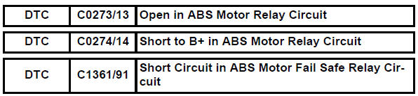
If a dtc related to the motor line is stored, the vsc fail (fail-safe) relay cuts off the power supply to the vsc mtr relay and performs the fail-safe operation.
While the abs, trc, vsc, or ba is operating, the skid control ecu turns the vsc fail relay on and activates the pump motor in the abs and traction actuator.
These dtcs may be stored if the motor relay (+bm) voltage becomes lower than the dtc detecting condition due to insufficient output from the battery or alternator.
Hint:
Dtcs c0273/13, c0274/14 and c1361/91: the skid control ecu begins to detect these dtcs when the vehicle speed exceeds 6 km/h (4 mph).
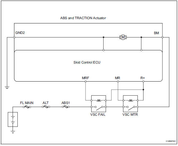
Wiring diagram
Inspection procedure
- Perform active test by intelligent tester (motor relay)
- Select the active test, generate a control command, and then check that the abs motor relay operates.

Ok: the operation sound of the abs motor can be heard.


- Inspect fuse (abs1)
- Remove the abs1 h-fuse from the engine room no. 1 Relay block.
- Measure the resistance of the fuse.
Standard resistance: below 1


- Inspect vsc motor relay (marking: vsc mtr)
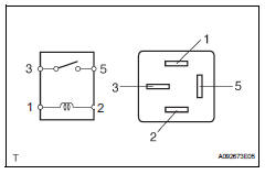
- Remove the vsc motor relay from the engine room no.
1 Relay block.
- Measure the resistance of the relay.
Standard resistance 


- Inspect fail-safe relay (marking: vsc fail)
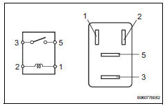
- Remove the faile-safe relay from the engine room no. 1 Relay block.
- Measure the resistance of the relay.
Standard resistance 


- Check wire harness (fail-safe relay - battery)
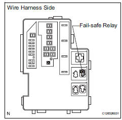
- Remove the fail-safe relay from the engine room no. 1 Relay block.
- Measure the voltage of the wire harness side connector.
Standard voltage 


- Check engine room no. 1 Relay block (fail-safe relay - vsc motor relay and body ground)
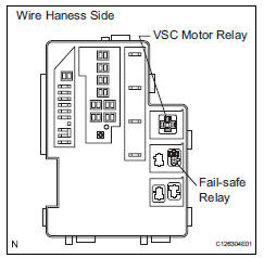
- Remove the fail-safe and vsc motor relays from the engine room no. 1 Relay block.
- Measure the resistance of the relay terminals.
Standard resistance 


- Check wire harness (engine room no. 1 Relay block - skid control ecu)
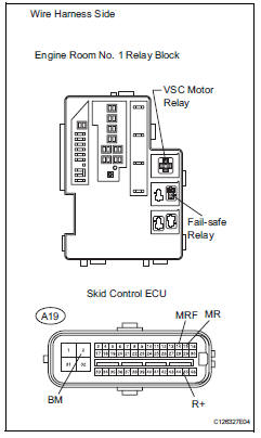
- Disconnect the a19 ecu connector.
- Remove the fail-safe and vsc motor relays from the engine room no. 1 Relay block.
- Measure the resistance of the wire harness connectors.
Standard resistance 


- Reconfirm dtc
- Clear the dtc(s) (see page bc-47).
- Start the engine
- Drive the vehicle at 6 km/h (4 mph) or more to activate the initial check.
- Check if the same dtc(s) is output (see page bc-47).
Result 


Replace abs and traction actuator assembly
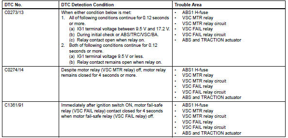
 Diagnostic trouble code chart
Hint:
If no abnormality is found when inspecting parts, check the
skid control ecu and check for poor contact at the ground
points.
If a dtc is displayed during the dtc check, check the
ci ...
 Open in abs solenoid relay circuit
Description
The solenoid relay supplies power to the abs solenoid and trc solenoid.
After the ignition switch is turned on, the vehicle speed has reached 6 km/h (4
mph) and the solenoid is
...
Other materials:
Installation
(2005/11-2006/01)
Install front drive shaft assembly lh
Coat the spline of the inboard joint shaft with gear
oil.
Using a brass bar and hammer, align the shaft
splines in the drive shaft.
Notice:
Set the snap ring with the opening side facing
downwards.
Be careful not to damage the oil s ...
Dtc check / clear
Check dtc (when using intelligent tester)
Connect the intelligent tester (with can vim) to the
dlc3.
Turn the ignition switch on.
Turn the tester on.
Read the dtcs by following the prompts on the
tester screen.
Hint:
Refer to the intelligent tester operator's manual for
furth ...
Short in driver side squib 2nd step circuit
Description
The driver side squib 2nd step circuit consists of the center airbag sensor,
the spiral cable and the
steering pad.
The circuit instructs the srs to deploy when the deployment conditions are met.
These dtcs are recorded when a malfunction is detected in the driver side squi ...
