Toyota RAV4 (XA40) 2013-2018 Service Manual: Short in driver side squib circuit
Description
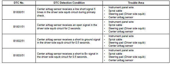
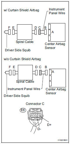
The driver side squib circuit consists of the center airbag sensor, the spiral cable and the steering pad.
The circuit instructs the srs to deploy when the deployment conditions are met.
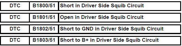
These dtcs are recorded when a malfunction is detected in the driver side squib circuit.
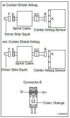
Wiring diagram

Inspection procedure
Hint:
- Perform the simulation method by selecting the "check mode" (signal check) with the intelligent tester (see page rs-52).
- After selecting the "check mode" (signal check), perform the simulation method by wiggling each connector of the airbag system or driving the vehicle on a city or rough road (see page rs-52).
- Check steering pad (driver side squib)
- Turn the ignition switch off.
- Disconnect the cable from the negative (-) battery terminal, and wait for at least 90 seconds.
- Disconnect the connectors from the steering pad.
- Connect the white wire side of sst (resistance 2.1 Ù) to connector e.
Caution:
Never connect a tester to the steering pad (driver side squib) for measurement, as this may lead to a serious injury due to airbag deployment.
Notice:
- Do not forcibly insert sst into the terminals of the connector when connecting.
- Insert sst straight into the terminals of the connector.
Sst 09843-18060
- Connect the cable to the negative (-) battery terminal, and wait for at least 2 seconds.
- Turn the ignition switch on (ig), and wait for at least 60 seconds.
- Clear the dtcs (see page rs-49).
- Turn the ignition switch off.
- Turn the ignition switch on, and wait for at least 60 seconds.
- Check the dtcs (see page rs-49).
Ok: dtc b1800, b1801, b1802, b1803 or 51 is not output.
Hint:
Dtcs other than dtc b1800, b1801, b1802, b1803 or 51 may be output at this time, but they are not related to this check.

- Check connector
- Turn the ignition switch off.
- Disconnect the cable from the negative (-) battery terminal, and wait for at least 90 seconds.
- Disconnect sst from the spiral cable.
- Check that the spiral cable connectors (on the steering pad side) are not damaged.
Ok: lock button is not disengaged, and claw of lock is not deformed or damaged.


- Check driver side squib circuit
- Disconnect the connectors from the center airbag sensor.
- Connect the cable to the negative (-) battery terminal, and wait for at least 2 seconds.
- Turn the ignition switch on.
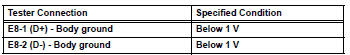
- Measure the voltage of the wire harness side connector
Standard voltage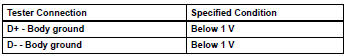
- Turn the ignition switch off.
- Disconnect the cable from the negative (-) battery terminal, and wait for at least 90 seconds.
- Measure the resistance of the wire harness side connector.
Standard resistance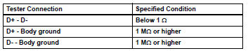
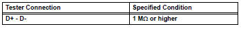
- Release the activation prevention mechanism built into connector b (see page rs-37).
- Measure the resistance of the wire harness side connector.
Standard resistance

- Check instrument panel wire
- Restore the released activation prevention mechanism of connector b to its original position.
- Disconnect the instrument panel wire connector from the spiral cable.
- Connect the cable to the negative (-) battery terminal, and wait for at least 2 seconds.
- Turn the ignition switch on.
- Measure the voltage of the wire harness side connector.
Standard voltage
- Turn the ignition switch off.
- Disconnect the cable from the negative (-) battery terminal, and wait for at least 90 seconds.
- Measure the resistance of the wire harness side connector.
Standard resistance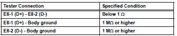
- Release the activation prevention mechanism built into connector b (see page rs-52).
- Measure the resistance of the wire harness side connector.
Standard resistance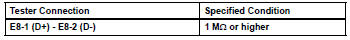

Replace spiral cable
 Passenger airbag on / off indicator circuit malfunction
Description
The passenger airbag on / off indicator circuit consists of the center airbag
sensor and the heater
control panel*1 or *2.
This circuit indicates the operation condition of the ...
 Short in front passenger side squib circuit
Description
The front passenger side squib circuit consists of the center airbag sensor
and the front passenger airbag.
The circuit instructs the srs to deploy when the deployment conditions ...
Other materials:
Problem symptoms table
Hint:
Use the table below to help determine the cause of the
problem symptom. The potential causes of the symptoms
are listed in order of probability in the "suspected area"
column of the table. Check each symptom by checking the
suspected areas in the order they are listed. Re ...
Door lock position circuit
Description
This circuit detects the state of the door lock detection sensor and sends it
to the main body ecu.
Wiring diagram
Inspection procedure
Read value of intelligent tester (door lock position)
Connect the intelligent tester (with can vim) to the
dlc3.
Turn the ignitio ...
Data list / active test
Read data list
Hint:
Using the intelligent tester's data list allows switch,
sensor, actuator and other item values to be read without
removing any parts. Reading the data list early in
troubleshooting is one way to save time.
Connect the intelligent tester (with can vim) to the
dlc3 ...
