Toyota RAV4 (XA40) 2013-2018 Service Manual: Second brake piston
Components
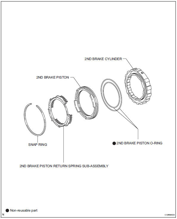
Disassembly
- Remove 2nd brake piston return spring sub-assembly
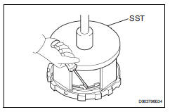
- Place sst on the return spring and compress.
- Using a screwdriver, pry out the snap ring.
- Remove the piston return spring.
- Inspect 2nd brake piston return spring sub-assembly (see page ax-223)
- Remove 2nd brake piston
- Hold the 2nd brake piston and apply compressed air (392 kpa, 4.0Kgf/cm2, 57 psi) to the 2nd brake cylinder to remove the 2nd brake piston.
- Remove 2nd brake piston o-ring
- Remove the 2 o-rings from the 2nd brake piston.
Inspection
- Inspect 2nd brake piston return spring sub-assembly
- Using a vernier caliper, measure the free length of the spring together with the spring seat.
Standard free length: 16.61 Mm (0.6539 In.)
Reassembly
- Install 2nd brake piston o-ring
- Coat the 2 new o-rings with atf, and install them into the 2nd brake piston.
- Install 2nd brake piston
- Press in the 2nd brake piston into the 2nd brake cylinder with your hands.
- Install 2nd brake piston return spring sub-assembly
- Install the piston return spring.
- Place sst on the piston return spring, and compress the piston return spring with a press.
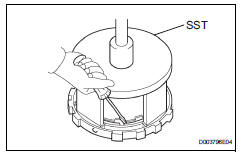
Sst 09387-00060
- Using a screwdriver, install the snap ring.
Notice:
Be sure the end gap of the snap ring is not aligned with the piston return spring claw.
 Reassembly
Install front oil pump oil seal
Using sst and a hammer, install a new oil seal to
the pump.
Sst 09350-32014 (09351-32140)
Hint:
The seal end should be flat with the outer edge of
...
 Forward clutch
Components
Disassembly
Inspect forward clutch (see page ax-227)
Remove forward multiple disc clutch disc
Using a screwdriver, remove the snap ring.
Remove the flange , 5 discs a ...
Other materials:
Steering angle sensor circuit malfunction
Description
The steering sensor signal is sent to the skid control ecu via the can
communication system. When
there is a malfunction in the can communication system, it is detected by the
steering sensor zero point
malfunction diagnostic function.
Wiring diagram
Inspection proce ...
Input speed sensor circuit no signal
Description
This sensor detects the rotation speed of the turbine, which shows the input
revolution of the transaxle. By
comparing the input speed signal (nt) with the counter gear speed sensor signal
(nc), the ecm detects
the shift timing of the gears and controls the engine torque and ...
Problem symptoms table (2006/01- )
Hint:
Use the table below to help determine the cause of the
problem symptom. The potential causes of the symptoms are
listed in order of probability in the "suspected area" column
of the table. Check each symptom by checking the suspected
areas in the order they are listed. Replace p ...
