Toyota RAV4 (XA40) 2013-2018 Service Manual: Removal
Hint:
- Use the same procedures for the rh side and lh side.
- The procedures listed below are for the lh side.
- Disconnect cable from negative battery terminal
Caution:
Wait at least 90 seconds after disconnecting the cable from the negative (-) battery terminal to prevent airbag and seat belt pretensioner activation.
- Remove rear door scuff plate lh (see page ir-26)
- Remove rear door opening trim weatherstrip lh
- Remove package tray trim pocket subassembly (w/o rear no. 2 Seat)
- Remove tonneau cover assembly (w/o rear no. 2 Seat)
- Remove rear floor no. 1 Board (w/o rear no.
2 Seat)
- Remove deck board assembly (w/o rear no. 2 Seat)
- Remove no. 2 Seat hinge cover lh (w/ rear no.
2 Seat) (see page se-109)
- Remove no. 2 Seat hinge cover rh (w/ rear no.
2 Seat) (see page ir-30)
- Remove no. 2 Seat leg cover lh (w/ rear no. 2 Seat) (see page se-109)
- Remove no. 2 Seat leg cover rh (w/ rear no. 2 Seat) (see page ir-30)
- Remove rear no. 2 Seat assembly lh (w/ rear no. 2 Seat) (see page se-110)
- Remove rear no. 2 Seat assembly rh (w/ rear no. 2 Seat) (see page se-110)
- Remove rear floor no. 2 Board
- Remove rear floor no. 3 Board
- Remove rear no. 1 Floor mat support side plate (see page ir-31)
- Remove back door weatherstrip
- Remove rear floor finish plate (see page ir- 31)
- Remove rear deck trim cover (w/ rear no. 2 Seat)
- Remove reclining remote control lever bezel lh (w/o rear no. 2 Seat)
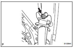
- Disconnect rear no. 1 Seat outer belt assembly rh
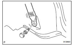
- Remove the lap belt outer anchor cover.
- Remove the bolt and disconnect the floor anchor.
- Disconnect rear no. 2 Seat outer belt assembly lh (w/ rear no. 2 Seat)
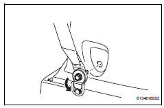
- Open the cover.
- Remove the bolt and disconnect the floor anchor.
- Remove deck trim side panel assembly lh (w/o rear no. 2 Seat) (see page ir-32)
- Remove deck trim side panel assembly lh (w/ rear no. 2 Seat) (see page ir-32)
- Remove inner roof side garnish assembly lh (w/o rear no. 2 Seat) (see page ir-34)
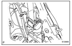
- Remove rear no. 2 Seat outer belt assembly lh (w/ rear no. 2 Seat)
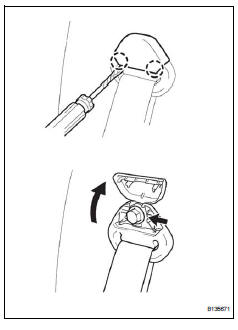
- Using a screwdriver, detach the 2 claws and open the seat belt anchor cover as shown in the illustration.
Hint:
Tape the screwdriver tip before use.
- Remove the bolt and disconnect the seat belt's shoulder anchor.
- Remove the 2 bolts and seat belt.
- Remove inner roof side garnish assembly lh (w/ rear no. 2 Seat) (see page ir-35)
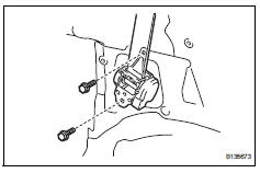
- Remove rear no. 1 Seat outer belt assembly lh
- Remove the bolt and disconnect the seat belt's shoulder anchor.
- Remove the 2 bolts and seat belt.
Inspection
- Inspect rear no. 1 Seat belt assembly outer
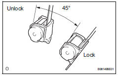
Notice:
Do not disassemble the retractor.
- When the inclination of the retractor is 15Đ or less,
check that the belt can be pulled from the retractor.
When the inclination of the retractor is over 45Ь check that the belt locks.
If the operation is not as specified, replace the belt.
- Inspect rear no. 2 Seat belt assembly outer
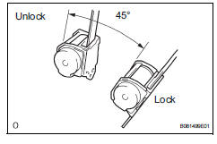
Notice:
Do not disassemble the retractor.
- When the inclination of the retractor is 15Đ or less,
check that the belt can be pulled from the retractor.
When the inclination of the retractor is over 45Ь check that the belt locks.
If the operation is not as specified, replace the belt.
 Rear seat outer belt assembly
Components
...
 Installation
Hint:
Use the same procedures for the lh side and rh side.
The procedures listed below are for the lh side.
A bolt without a torque specification is shown in the
standard bolt chart (see pag ...
Other materials:
System description
Brief description
The can (controller area network) is a serial data
communication system for real time application. It is
a vehicle multiplex communication system which
has a high communication speed (500 kbps) and
the ability to detect malfunctions.
By pairing the canh and canl ...
Engine compartment
Engine coolant reservoir
Engine oil filler cap
Battery
Brake fluid reservoir
Fuse box
Radiator
Condenser
Electric cooling fans
Engine oil level dipstick
Washer fluid tank
Engine oil
With the engine at operating temperature and turned off, check the oil
level on the dips ...
Tc and cg terminal circuit
Description
Dtc output mode is set by connecting terminals tc and cg of the dlc3.
The dtcs are displayed by blinking the srs warning light.
Hint:
Make sure that dtc b1281 has not been output. If dtc b1281 has been
output, refer to the multiplex
communication system.
When each warning ...
