Toyota RAV4 (XA40) 2013-2018 Service Manual: Rear no. 2 Suspension arm
Components
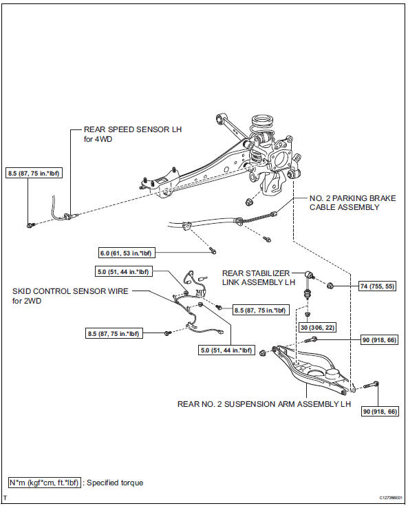
Removal
Hint:
- Use the same procedures for the rh side and lh side.
- The procedures listed below are for the lh side.
- Remove rear wheel
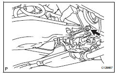
- Disconnect no. 2 Parking brake cable assembly (see page pb-8)
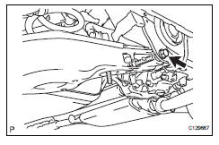
- Disconnect skid control sensor wire (for 2wd) (see page bc-198)
- Disconnect rear speed sensor lh (for 4wd) (see page bc-205)
- Disconnect rear stabilizer link assembly lh (see page sp-50)
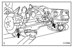
- Disconnect rear no. 2 Suspension arm assembly lh
- Loosen the bolt from the suspension member side.
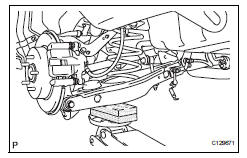
- Support the no. 2 Suspension arm lh with a jack.
Notice:
Place a wooden or rubber block between the jack and the arm.

- Remove the bolt and nut from the axle carrier side.
- Slowly lower the jack, and disconnect the no. 2 Suspension arm from the axle carrier.
- Remove rear coil spring insulator upper lh (see page sp-33)
- Remove rear coil spring lh (see page sp-33)
- Remove rear coil spring insulator lower lh (see page sp-33)
- Remove rear no. 2 Suspension arm assembly lh
- Remove the bolt, nut and suspension arm from the suspension member.
Installation
Hint:
- Use the same procedures for the rh side and lh side.
- The procedures listed below are for the lh side.
- Temporarily install rear no. 2 Suspension arm assembly lh
- Temporarily install the no. 2 Suspension arm with the bolt and nut to the suspension member.
- Install rear coil spring insulator lower lh (see page sp-34)
- Install rear coil spring lh (see page sp-34)
- Install rear coil spring insulator upper lh (see page sp-34)
- Install rear no. 2 Suspension arm assembly lh
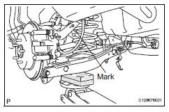
- Slowly raise the jack, and install the no. 2 Suspension arm to the axle carrier.
Notice:
Install the arm so that the coil spring's distinguishing mark is on the outer side of the vehicle.
- Install rear stabilizer link assembly lh (see page sp-52)
- Connect skid control sensor wire (for 2wd) (see page bc-198)
- Connect rear speed sensor lh (for 4wd) (see page bc-205)
- Connect no. 2 Parking brake cable assembly (see page pb-8)
- Install rear wheel
- Install the wheel.
Torque: 103 n*m (1,050 kgf*cm, 76 ft.*Lbf)
- Stabilize suspension (see page sp-37)
- Tighten rear no. 2 Suspension arm assembly lh
- Install the 2 nuts and 2 bolts.
Torque: 90 n*m (918 kgf*cm, 66 ft.*Lbf)
Notice:
Do not tighten the nuts.
- Inspect and adjust rear wheel alignment
- Inspect and adjust the rear wheel alignment (see page sp-7).
 Rear no. 1 Suspension arm
Components
Removal
Hint:
Use the same procedures for the rh side and lh side.
The procedures listed below are for the lh side.
Remove rear wheel
Remove rear no. 1 Suspension arm as ...
 Suspension & axle rear stabilizer bar
Components
...
Other materials:
Removal (2005/11-2006/01)
Disconnect cable from negative battery
terminal
Caution:
Wait at least 90 seconds after disconnecting the
cable from the negative (-) battery terminal to
prevent airbag and seat belt pretensioner activation.
Remove air cleaner case sub-assembly
Remove the air cleaner case (see ...
Reassembly (2006/01- )
Install drive shaft bearing case subassembly
(for rh)
Install the bearing snap ring.
Using sst and a press, press in the drive shaft
bearing case to the inboard joint rh.
Sst 09527-10011, 09710-04081
Notice:
The bearing should be installed completely.
Using a snap rin ...
Random / multiple cylinder misfire detected
Description
When the engine misfires, high concentrations of hydrocarbons (hc) enter the
exhaust gas. Extremely
high hc concentration levels can cause increases in exhaust emission levels.
High concentrations of hc
can also cause increases in the three-way catalytic converter (twc) te ...
