Toyota RAV4 (XA40) 2013-2018 Service Manual: Radiator
Components
On-vehicle inspection
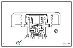
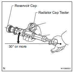
- Check radiator reservoir cap subassembly
- Measure the valve opening pressure.
- If there are water stains or foreign matter on oring 1, clean it with water and finger scouring.
- Check that o-ring 1 is not deformed, cracked or swollen.
- Apply engine coolant to o-ring 1 and rubber packing 2 before using a radiator cap tester.
- When using the cap tester, tilt it more than 30 degrees.
- Pump the cap tester several times, and check the maximum pressure*.
Pump speed: 1 pump per second
*: Even if the cap cannot maintain the maximum pressure, it is not a defect.
Judgment criterion 
If the maximum pressure is less than the minimum standard value, replace the radiator reservoir cap sub-assembly.
On-vehicle cleaning
- Inspect radiator assembly
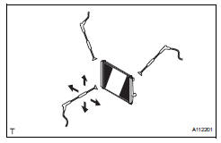
- Check that the radiator and condenser are not blocked with leaves, dirt, or insects. Clean the hose connections.
If the fins are blocked, wash them with water or a steam cleaner.
Notice:
- If the distance between the steam cleaner and core is too close, the fins may be damaged.
- Keep the following injection distance.
Standard injection distance 
- If the fins are bent, straighten them with a screwdriver or pliers.
- Never apply water directly onto the electronic components.
- Dry the fins with compressed air.
Removal
- Disconnect cable from negative battery terminal
Caution:
Wait at least 90 seconds after disconnecting the cable from the negative (-) battery terminal to prevent airbag and seat belt pretensioner activation.
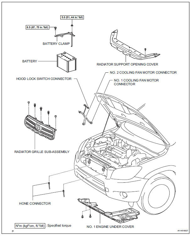
- Remove radiator support opening cover
- Remove battery clamp
- Remove the bolt, nut and clamp.
- Remove battery
- Remove no. 1 Engine under cover
- Drain engine coolant (see page co-6)
- Remove radiator grille sub-assembly (see page et-6)
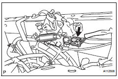
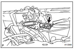
- Disconnect hood lock switch connector
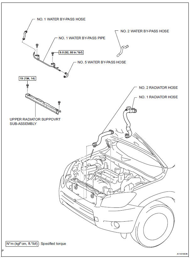
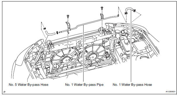
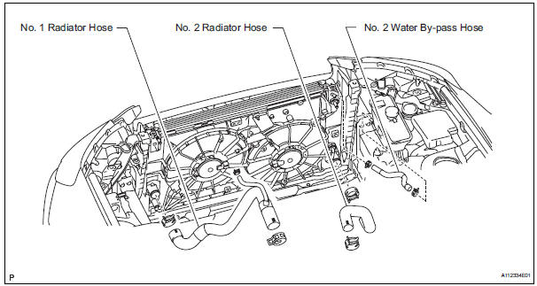
- Disconnect no. 1 Water by-pass hose
- Disconnect the hose from the radiator reservoir.
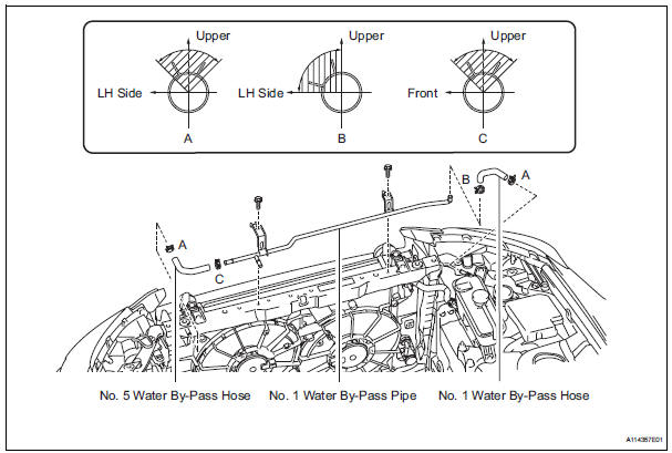
- Disconnect no. 5 Water by-pass hose
- Disconnect the hose from the radiator.
- Remove no. 1 Water by-pass pipe
- Disconnect the pipe from the no. 1 Radiator hose.
- Remove the 2 bolts and the pipe.
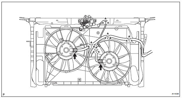
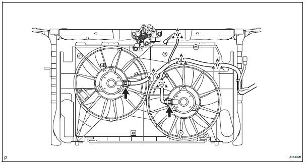
- Disconnect cooling fan motor harness
- Disconnect the 2 fan motor connectors from the 2 fan motors.
- Detach the 5 harness clamps from the fan shroud and upper radiator support.
- Disconnect horn connector
- Disconnect the 2 horn connectors.
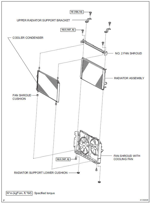
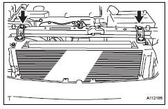
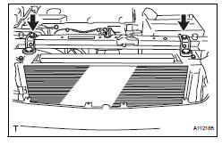
- Remove upper radiator support bracket
- Remove the 2 bolts and the 2 upper radiator support brackets.
- Remove no. 2 Fan shroud
- Remove the 2 bolts.
- Detach the 2 claws and no. 2 Shroud.
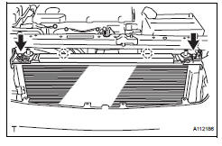
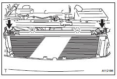
- Remove upper radiator support subassembly
- Remove the 4 bolts and upper radiator support with hood lock.
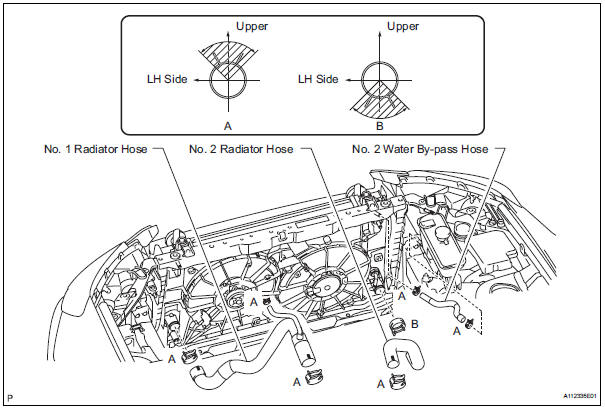
- Disconnect no. 1 Radiator hose
- Disconnect no. 2 Radiator hose
- Disconnect no. 2 Water by-pass hose
Disconnect the by-pass hose from the radiator reservoir and radiator.
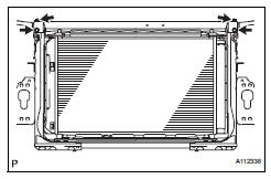
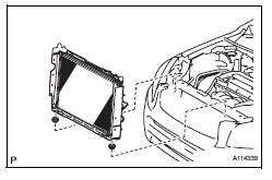
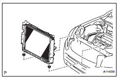
- Remove radiator assembly
- Separate the cooler condenser from the radiator.
Hint:
After detaching the condenser, make sure that all 4 fan shroud cushions are present
- Remove the radiator with the 2 radiator support lowers.
Hint:
After detaching the radiator, make sure that both radiator support lowers are present.
- Remove fan shroud with cooling fan
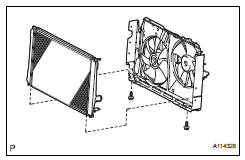
- Remove the 2 bolts and radiator from the fan shroud.
Installation
- Install fan shroud with cooling fan
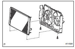
- Install the fan shroud with cooling fan with the 2 bolts to the radiator.
Torque: 10.5 N*m (107 kgf*cm, 8 ft.*Lbf)
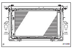
- Install radiator assembly
- Install the 4 fan shroud cushions to the cooler condenser.
- Set the cooler condenser to the fan shroud.
- Install the 2 radiator support lower cushions to the fan shroud.
- Install the radiator with cooler condenser and fan shroud to the radiator support lower.
- Install upper radiator support subassembly
- Install the upper radiator support with the 4 bolts.
Torque: 19 n*m (194 kgf*cm, 14 ft.*Lbf)
- Install no. 2 Fan shroud
- Attach the 2 claws to install the no. 2 Fan shroud and install the 2 bolts.
Torque: 10.5 N*m (107 kgf*cm, 8 ft.*Lbf)
- Install upper radiator support bracket
- Install the bracket with the 2 bolts.
Torque: 19 n*m (194 kgf*cm, 14 ft.*Lbf)
- Connect horn connector
- Connect the 2 horn connectors.
- Connect no. 2 Water by-pass hose
- Connect the by-pass hose to the radiator and radiator reservoir.
Hint:
The direction of the hose clamp is indicated in the illustration.
- Connect no. 2 Radiator hose
Hint:
The direction of the hose clamp is indicated in the illustration.
- Connect no. 1 Radiator hose
Hint:
The direction of the hose clamp is indicated in the illustration.
- Connect cooling fan motor harness
- Attach the harness with the 5 clamps.
- Connect the 2 fan motor connectors.
- Install no. 1 Water by-pass pipe
- Install the by-pass pipe with the 2 bolts to the upper radiator support.
Torque: 9.0 N*m (92 kgf*cm, 80 in.*Lbf)
- Connect the no. 1 Radiator hose to the pipe.
Hint:
The direction of the hose clamp is indicated in the lustration.
- Connect no. 5 Water by-pass hose
- Connect the by-pass hose to the radiator.
Hint:
The direction of the hose clamp is indicated in the lustration.
- Connect no. 1 Water by-pass hose
- Connect the by-pass hose to the radiator and radiator reservoir.
Hint:
The direction of the hose clamp is indicated in the illustration.
- Connect hood lock switch connector
- Install radiator grille sub-assembly (see page et-10)
- Install battery
- Install battery clamp
- Attach the hook of the battery clamp to the battery bracket.
- Temporarily tighten the nut and install the bolt.
- Adjust the battery clamp's position.
- Fully tighten the bolt and nut.
Torque: 8.5 N*m (87 kgf*cm, 75 in.*Lbf) for bolt 5.0 N*m (51 kgf*cm, 44 in.*Lbf) for nut
- Connect cable to negative battery terminal
- Add engine coolant (see page co-6)
- Check for engine coolant leaks (see page co-1)
- Install radiator support opening cover
 Cooling fan relay
On-vehicle inspection
Disconnect cable from negative battery
terminal
Caution:
Wait at least 90 seconds after disconnecting the
cable from the negative (-) battery terminal to
prevent airb ...

Other materials:
Front door courtesy switch
Components
Removal
Hint:
Use the same procedures for the rh and lh sides.
The procedures listed below are for the lh side.
Disconnect cable from negative battery
terminal
Caution:
Wait at least 90 seconds after disconnecting the
cable from the negative (-) battery terminal t ...
Road test
Inspect set switch
Push the main switch on.
Drive at a desired speed (40 km/h (25 mph) or
higher).
Inspect "+" switch
Push the main switch button on.
Drive at a desired speed (40 km/h (25 mph) or
higher).
Press the control switch to -/set. ...
Unmatched encryption code
Description
This dtc is output when a key with an incomplete key code is inserted into
the ignition key cylinder.
Inspection procedure
Reregister key
Clear the dtc (see page ei-18).
Reregister the key code with the transponder key ecu
(see page ei-5)
Check that the engine ...
