Toyota RAV4 (XA40) 2013-2018 Service Manual: Key lock-in prevention function does not work properly
Description
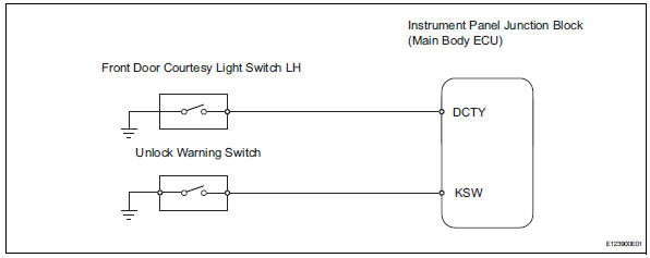
When the key is in the ignition key cylinder or the door courtesy light on signal is output to the main body ecu, performing the door lock operation with the lock switch does not lock the door.
Wiring diagram
Inspection procedure
- Read value of intelligent tester (unlock warning switch)
- Use the data list to check if the unlock warning switch is functioning properly.
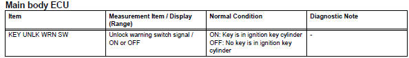
Ok: when the switch is operating, the intelligent tester should display as shown in the table.


- Read value of intelligent tester (driver side door courtesy light switch)
- Use the data list to check if the door courtesy light switch is functioning properly.
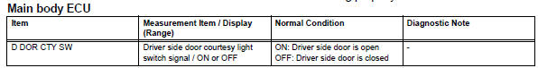
Ok: when the switch is operating, the intelligent tester should display as shown in the table.

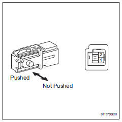
- Inspect front door courtesy light switch assembly lh
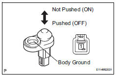
- Remove the front door courtesy light switch.
- Measure the resistance of the switch.
Standard resistance 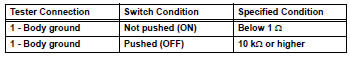

- Check wire harness (ecu - switch)
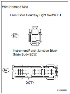
- Disconnect the k7 switch connector.
- Disconnect the ia junction block connector.
- Measure the resistance of the wire harness side connectors.
Standard resistance 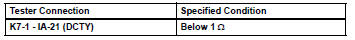

Replace instrument panel junction block (main body ecu)
- Inspect unlock warning switch assembly
- Remove the unlock warning switch.
- Measure the resistance of the switch.
Standard resistance 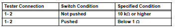

- Check wire harness (switch - ecu)
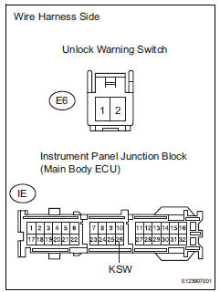
- Disconnect the e6 switch connector.
- Disconnect the ie junction block connector.
- Measure the resistance of the wire harness side connectors.
Standard resistance 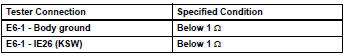

Replace instrument panel junction block (main body ecu)
 Only back door lock / unlock functions do not operate
Description
The main body ecu receives lock / unlock switch signals and activates the
door lock motor accordingly.
Wiring diagram
Inspection procedure
Inspect back door with motor lock as ...
 Key reminder warning system
Parts location
System diagram
...
Other materials:
Slip indicator light does not come on
Description
Refer to the description of "slip indicator light remains on" (see page
bc-152).
Wiring diagram
Refer to the slip indicator light circuit (see page bc-152).
Inspection procedure
Notice:
When replacing the abs and traction actuator, perform the zero point
calibration ( ...
Throttle / pedal position sensor
Hint:
These dtcs relate to the accelerator pedal position (app) sensor.
Description
Hint:
This etcs (electronic throttle control system) does not use a throttle cable.
The app sensor is mounted on the accelerator pedal bracket and has 2 sensor
circuits: vpa (main) and
vpa2 (sub). This ...
Riding with children
Observe the following precautions
when children are
in the vehicle.
Use a child restraint system
appropriate for the child,
until the child becomes
large enough to properly
wear the vehicle's seat belt.
It is recommended that children
sit in the rear seats to
avoid accidental contact
with the ...
