Toyota RAV4 (XA40) 2013-2018 Service Manual: Illumination circuit
Description
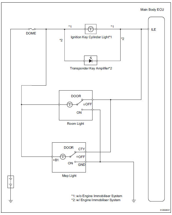
The main body ecu receives information regarding the door courtesy switch and door lock position switch, and turns on the room light.
Wiring diagram
Inspection procedure
- Perform active test by intelligent tester (main body ecu)
- Connect the intelligent tester (with can vim) to the dlc3.
- Turn the ignition switch to the on position and press the intelligent tester main switch on.
- Select the items below in the active test and then check the main body ecu operation.
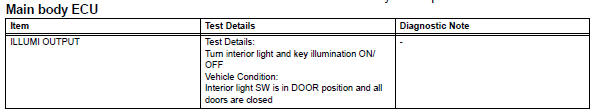
Ok: light comes on.

- Inspect fuse (dome)
- Remove the dome fuse from the engine room no. 2 Relay block.
- Measure the resistance of the fuse.
Standard resistance:
below 1 

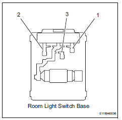
- Inspect room light assembly
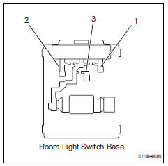
- Remove the room light assembly
- Measure the resistance of the room light switch base.
Standard resistance 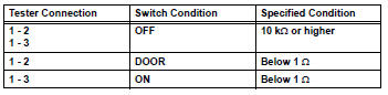


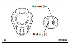
- Inspect room light bulb
- Remove the room light assembly.
- Connect the positive (+) lead from the battery to terminal 1 and the negative (-) lead to terminal 2, then check that the light comes on when the switch is in the door position.
Ok: light comes on.
- Connect the positive (+) lead from the battery to terminal 1 and the negative (-) lead to terminal 3, then check that the light comes on when the switch is in the on position.
Ok: light comes on.

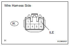
- Check harness and connector (battery - room light and main body ecu)
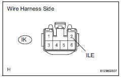
- Disconnect the ik instrument panel junction block connector.
- Measure the voltage of the wire harness side connector.
Standard voltage 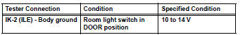

- Inspect map light bulb
- Remove the map light assembly.
- Connect the positive (+) lead from the battery to terminal 6 and the negative (-) lead to terminal 1, then check that the light comes on when the switch is in the door position.
Ok: light comes on.
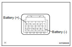
- Connect the positive (+) lead from the battery to terminal 6 and the negative (-) lead to terminal 7, then check that the light comes on when the switch is in the on position.
Ok: light comes on.


- Inspect map light
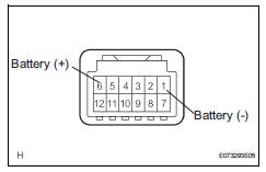
- Replace the map light bulb with a normally functioning one or a new one.
- Connect the positive (+) lead from the battery to terminal 6 and the negative (-) lead to terminal 1, then check that the light comes on when the switch is in the door position.
Ok: light comes on.
- Connect the positive (+) lead from the battery to terminal 6 and the negative (-) lead to terminal 7, then check that the light comes on when the switch is in the on position.
Ok: light comes on.

Replace map light bulb
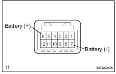
- Check wire harness (battery - map light and main body ecu)
- Disconnect the ik instrument panel junction block connector.
- Measure the voltage of the wire harness side connector.
Standard voltage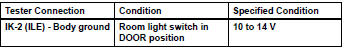

- Inspect ignition key cylinder light
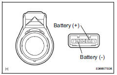
- W/ engine immobiliser system
- Remove the transponder key amplifier (ignition key cylinder light).
- Connect the positive (+) lead from the battery to terminal 2 and the negative (-) lead to terminal 6, then check that the light comes on.
Ok: light comes on.
- W/o engine immobiliser system
- Remove the ignition key cylinder light.
- Connect the positive (+) lead from the battery to terminal 2 and the negative (-) lead to terminal 1, then check that the light comes on.
Ok: light comes on.

- Check wire harness (battery - main body ecu)
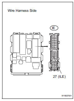
- Disconnect the ie instrument panel junction block connector.
- Measure the voltage of the wire harness side connector.
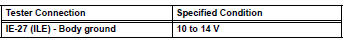

Replace instrument panel junction block
 Footwell light circuit
Description
The main body ecu receives information regarding the door lock position
switch and ignition switch, and
turns on each foot light.
Wiring diagram
Inspection procedure
Perform ...
 Taillight relay circuit
Description
When the light control switch, located on the headlight dimmer switch, is
turned to the tail position, the
taillight relay (marking: t-lp) turns on to illuminate the front side marker ...
Other materials:
Cooling fan relay
On-vehicle inspection
Disconnect cable from negative battery
terminal
Caution:
Wait at least 90 seconds after disconnecting the
cable from the negative (-) battery terminal to
prevent airbag and seat belt pretensioner activation.
Remove engine room no. 2 Relay block
cover
Inspect ...
Rear center seat outer belt assembly
Components
Removal
Caution:
Wait at least 90 seconds after disconnecting the cable
from the negative (-) battery terminal to prevent airbag
and seat belt pretensioner activation.
Remove shoulder belt anchor cover rh
Using a screwdriver, remo ...
Driver side seat belt buckle switch circuit malfunction
Description
The driver side seat belt buckle switch circuit consists of the center airbag
sensor and the front seat inner
belt lh.
Dtc b1655/37 is recorded when a malfunction is detected in the driver side seat
belt buckle switch circuit.
Wiring diagram
Inspection procedure
...
