Toyota RAV4 (XA40) 2013-2018 Service Manual: Front fog light circuit
Description
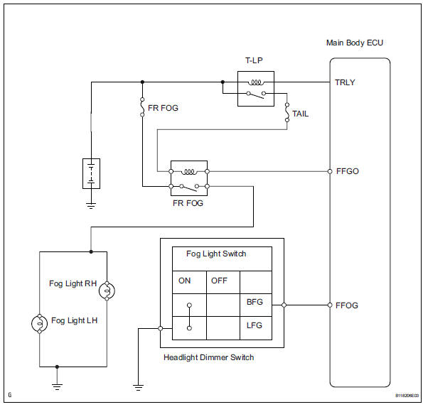
The main body ecu controls the front fog light relay (marking: fr fog) when a signal is received from the headlight dimmer switch.
Wiring diagram
Inspection procedure
- Perform active test by intelligent tester
- Connect the intelligent tester (with can vim) to the dlc3.
- Turn the ignition switch to the on position and press the intelligent tester main switch on.
- Select the item below in the active test and then check the relay operation.

Ok: front fog light comes on.

- Check taillight
- Check that the taillight comes on when the light control switch is on (tail).
Ok: taillight comes on.

- Inspect fuse (fr fog)
- Remove the fr fog fuse from the instrument panel junction block.
- Measure the resistance of the fuses.
Standard resistance:
below 1 


- Inspect fog light bulb
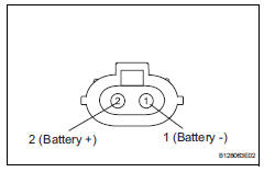
- Remove the fog light bulb.
- Connect the positive (+) lead from the battery to terminal 2 and the negative (-) lead to terminal 1, then check that the bulb illuminates.
Ok: bulb illuminates.


- Inspect front fog light relay (marking: fr fog)
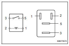
- Remove the front fog light relay from the no. 6 Relay block.
- Measure the resistance of the relay.
Standard resistance 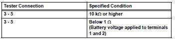

- Check wire harness (battery - main body ecu)
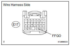
- Disconnect the e17 ecu connector.
- Measure the voltage of the wire harness side connector.
Standard voltage 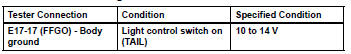

- Check wire harness (front fog light relay - battery)
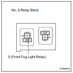
- Remove the front fog light relay from the no. 6 Relay block.
- Measure the voltage of the relay block.
Standard voltage 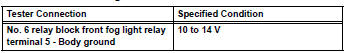

- Check wire harness (front fog light relay - front fog light and body ground)
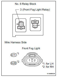
- Remove the front fog light relay from the no. 6 Relay block.
- Disconnect the a11 and a28 front fog light connectors.
- Measure the resistance of the wire harness side connectors.
Standard resistance 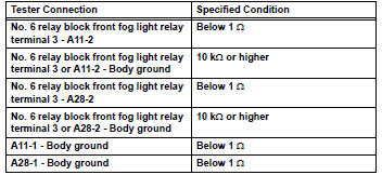

Replace instrument panel junction block (main body ecu)
- Check wire harness (dimmer switch - main body ecu and body ground)
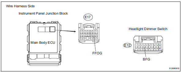
- Disconnect the e12 headlight dimmer switch connector.
- Disconnect the e17 main body ecu connector.
- Measure the resistance of the wire harness side connectors.
Standard resistance 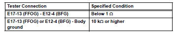

- Inspect fog light switch
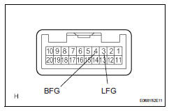
- Remove the headlight dimmer switch.
- Measure the resistance of the switch.
Standard resistance 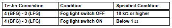

Repair or replace harness and connector (headlight dimmer switch - body ground)
 Headlight (hi-beam) circuit
Description
The body ecu controls the headlight relay, no. 2 Daytime running light relay
(marking: drl no. 2) And
no. 4 Daytime running light relay (marking: drl no. 4).
Wiring diagram
I ...
 Turn signal light circuit
Description
The turn signal flasher relay (marking: flsh) in the main body ecu turns on
when it receives signals
from the headlight dimmer switch integrated with the turn signal switch, causing
...
Other materials:
Components (2005/11-2006/01)
Sliding roof ecu power source circuit
Description
If the sliding function and tilt function do not operate, there may be a
malfunction in the sliding roof ecu
power source circuit.
Wiring diagram
Inspection procedure
Perform active test by i ...
Position initialization incomplete
Description
This dtc is output when the sliding roof drive gear (sliding roof ecu) has
not been initialized.
Wiring diagram
Refer to dtc b2341 (see page rf-11).
Inspection procedure
Initialize sliding roof drive gear sub-assembly (sliding roof ecu)
Check that the sliding roof ...
If your vehicle overheats
The following may indicate that your vehicle is overheating.
The high engine coolant temperature warning light Comes
on or a loss of engine power is experienced. (For example, the
vehicle speed does not increase.)
Steam comes out from under the hood.
Correction procedures
Stop ...
