Toyota RAV4 (XA40) 2013-2018 Service Manual: Front axle hub
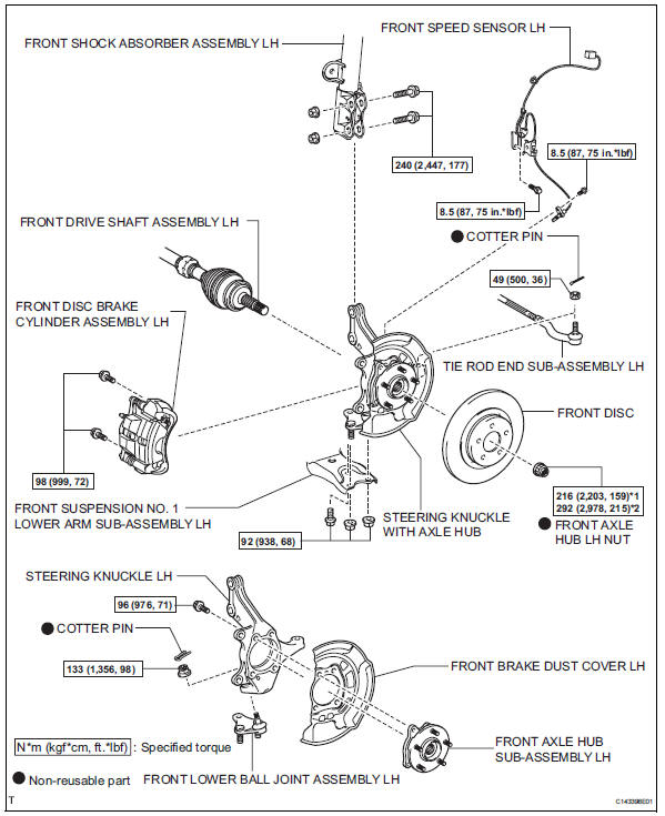
Components (2005/11-2006/01)
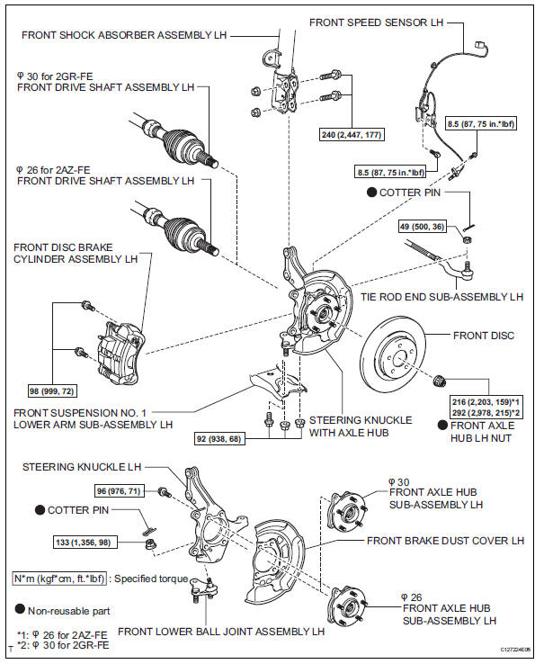
Components (2006/01- )
On-vehicle inspection
- Check front axle hub bearing
- Remove the front wheel.
- Disconnect the front disc brake cylinder (see page br-40).
- Remove the front disc.
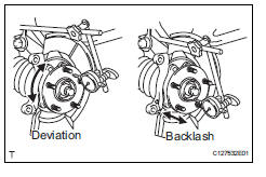
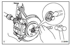
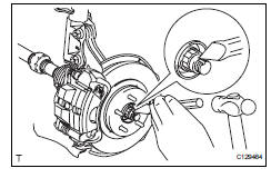
- Inspect the axle hub backlash.
- Using a dial indicator, check the backlash near the center of the axle hub.
Maximum backlash: 0.05 Mm (0.0020 In.)
If the backlash is greater than the maximum, replace the bearing.
- Inspect the axle hub deviation.
- Using a dial indicator, check the deviation on the surface of the axle hub.
Maximum deviation: 0.05 Mm (0.0020 In.)
If the deviation is greater than the maximum, replace the bearing.
Removal (2005/11-2006/01)
Hint:
- Use the same procedures for the rh side and lh side.
- The procedures listed below are for the lh side.
- Remove front wheel
- Drain automatic transaxle fluid
- Drain the automatic transaxle fluid for u140f (see page ax-147).
- Drain the automatic transaxle fluid for u241e (see page ax-146).
- Disconnect cable from negative battery terminal
Caution:
Wait at least 90 seconds after disconnecting the cable from the negative (-) battery terminal to prevent airbag and seat belt pretensioner activation.
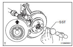
- Remove front axle hub nut
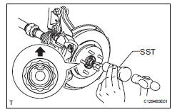
- Using sst and a hammer, unstake the staked part of the nut.
Sst 09930-00010
Notice:
Loosen the staked part of the nut completely, otherwise the screw of the drive shaft may be damaged.
- While applying the brakes, remove the lock axle hub nut.
- Remove front speed sensor lh (see page bc- 191)
- Remove front disc brake cylinder assembly lh (see page br-40)
- Remove front disc (see page br-42)
- Disconnect tie rod end sub-assembly lh (see page ps-42)
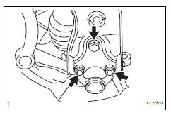
- Disconnect front suspension no. 1 Lower arm sub-assembly lh
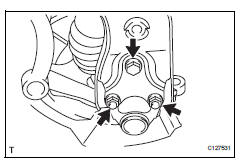
- Remove the bolt and 2 nuts.
- Disconnect the lower arm from the ball joint.
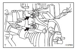
- Remove steering knuckle with axle hub
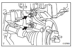
- Remove the 2 bolts and 2 nuts, and disconnect the shock absorber from the steering knuckle.
Hint:
While fixing the nuts in place, loosen and remove the bolts.
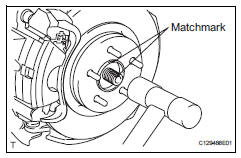
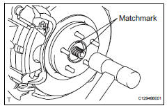
- Put matchmarks on the drive shaft and the axle hub.
- Using a plastic-faced hammer, remove the steering knuckle with axle hub.
Notice:
Be careful not to damage the boot and speed sensor rotor. Do not excessively push out the drive shaft from the axle assembly.
- Remove front lower ball joint assembly lh (see page sp-27)
- Remove front axle hub sub-assembly lh
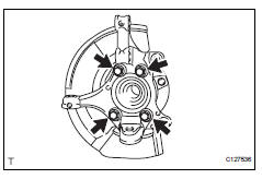
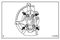
- Remove the 4 bolts and axle hub from the steering knuckle.
Notice:
Do not place the hub and bearing's magnet rotor side so that it is facing downward, and do not allow the magnet rotor side to become damaged or contact foreign matter.
- Remove the dust cover from the steering knuckle.
Removal (2006/01- )
Hint:
- Use the same procedures for the rh side and lh side.
- The procedures listed below are the lh side.
- Remove front wheel
- Drain automatic transaxle fluid
- Drain the automatic transaxle fluid for u140f (see page ax-147).
- Drain the automatic transaxle fluid for u241e (see page ax-146).
- Drain the automatic transaxle fluid for u151e (see page ax-172).
- Drain the automatic transaxle fluid for u151f (see page ax-173).
- Disconnect cable from negative battery terminal
Caution:
Wait at least 90 seconds after disconnecting the cable from the negative (-) battery terminal to prevent airbag and seat belt pretensioner activation.
- Remove front axle hub lh nut
- Using sst and a hammer, unstake the staked part of the nut.
Sst 09930-00010
Notice:
Loosen the staked part of the nut completely, otherwise the screw of the drive shaft may be damaged.
- While applying the brakes, remove the lock axle hub nut.
- Remove front speed sensor lh (see page bc- 191)
- Remove front disc brake cylinder assembly lh (see page br-40)
- Remove front disc (see page br-42)
- Disconnect tie rod end sub-assembly lh (see page ps-42)
- Disconnect front suspension no. 1 Lower arm sub-assembly lh
- Remove the bolt and 2 nuts.
- Disconnect the lower arm from the ball joint.
- Remove steering knuckle with axle hub
- Remove the 2 bolts and 2 nuts, and disconnect the shock absorber from the steering knuckle.
Hint:
While fixing the nuts in place, loosen and remove the bolts.
- Put matchmarks on the drive shaft and axle hub.
- Using a plastic-faced hammer, remove the steering knuckle with axle hub.
Notice:
Be careful not to damage the boot and speed sensor rotor. Do not excessively push out the drive shaft from the axle assembly.
- Remove front lower ball joint assembly lh (see page sp-27)
- Remove front axle hub sub-assembly lh
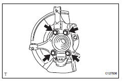
- Remove the 4 bolts and axle hub from the steering knuckle.
Notice:
Do not place the hub and bearing's magnet rotor side so that it is facing downward, and do not allow the magnet rotor side to become damaged or contact foreign matter.
- Remove the dust cover from the steering knuckle.
Installation (2005/11-2006/01)
Hint:
- Use the same procedures for the rh side and lh side.
- The procedures listed below are for the lh side.
- Install front axle hub sub-assembly lh
- Install the dust cover to the steering knuckle.
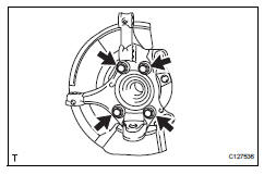
- Install the axle hub with the 4 bolts.
Torque: 96 n*m (979 kgf*cm, 1 ft.*Lbf)
Notice:
Do not place the hub and bearing's magnet rotor side so that it is facing downward, and do not allow the magnet rotor side to become damaged or contact foreign matter.
- Install front lower ball joint assembly lh (see page sp-28)
- Install steering knuckle with axle hub
- Align the shaft splines and drive in the drive shaft.
- Install the steering knuckle with axle hub with the 2 bolt and 2 nuts.
Torque: 240 n*m (2,447 kgf*cm, 177 ft.*Lbf)
Notice:
Do not tighten the nuts.
- Connect front suspension no. 1 Lower arm sub-assembly lh
- Connect the lower arm to the ball joint with the 2 bolts and nut.
Torque: 92 n*m (938 kgf*cm, 68 ft.*Lbf)
- Connect tie rod end sub-assembly lh (see page ps-45)
- Install front speed sensor lh (see page bc- 193)
- Check front axle hub bearing
- Check the axle hub bearing (see page ah-6).
- Install front disc (see page br-43)
- Install front disc brake cylinder assembly lh (see page br-46)
- Install front axle hub nut
- Install a new hub nut.
Torque: 216 n*m (2,203 kgf*cm, 159 ft.*Lbf)
- Using a chisel and hammer, stake the hub nut.
- Install front wheel torque: 103 n*m (1,050 kgf*cm, 6 ft.*Lbf)
- Inspect and adjust front wheel alignment
- Inspect and adjust the wheel alignment (see page sp-3).
- Connect cable to negative battery terminal
- Check speed sensor signal
- Check the speed sensor signal (see page bc-44).
Installation (2006/01- )
Hint:
- Use the same procedures for the rh side and lh side.
- The procedures listed below are the lh side
- Install front axle hub sub-assembly lh
- Install the dust cover to the steering knuckle.
- Install the axle hub with the 4 bolts.
Torque: 96 n*m (979 kgf*cm, 71 ft.*Lbf)
Notice:
Do not place the hub and bearing's magnet rotor side so that it is facing downward, and do not allow the magnet rotor side to become damaged or contact foreign matter.
- Install front lower ball joint assembly lh (see page sp-28)
- Install steering knuckle with axle hub
- Align the shaft splines and drive in the drive shaft.
- Install the steering knuckle with axle hub with the 2 bolts and 2 nuts.
Torque: 240 n*m (2,447 kgf*cm, 177 ft.*Lbf)
Notice:
Do not tighten the bolts.
- Connect front suspension no. 1 Lower arm sub-assembly lh
- Connect the lower arm to the ball joint with the bolt
and 2 nuts.
Torque: 92 n*m (938 kgf*cm, 68 ft.*Lbf)
- Connect tie rod end sub-assembly lh (see page ps-45)
- Install front speed sensor lh (see page bc- 193)
- Check front axle hub bearing
- Check the axle hub bearing (see page ah-6).
- Install front disc (see page br-43)
- Install front disc brake cylinder assembly lh (see page br-46)
- Install front axle hub lh nut
- Install a new hub nut.
Torque: 216 n*m (2,203 kgf*cm, 159 ft.*Lbf) for ö 26 for 2az-fe
292 N*m (2,978 kgf*cm, 215 ft.*Lbf) for ö 30 for 2gr-fe
- Using a chisel and hammer, stake the hub nut.
- Add automatic transaxle fluid
- Add the automatic transaxle for u140f (see page ax-152).
- Add the automatic transaxle for u241e (see page ax-151).
- Add the automatic transaxle for u151e (see page ax-177).
- Add the automatic transaxle for u151f (see page ax-178).
- Check for automatic transaxle fluid leakage
- Install front wheel torque: 103 n*m (1,050 kgf*cm, 76 ft.*Lbf)
- Inspect and adjust front wheel alignment
- Inspect and adjust the front wheel alignment (see page sp-3).
- Connect cable to negative battery terminal
- Check speed sensor signal
- Check the speed sensor signal (see page bc-44).
 Front axle hub bolt
Components
Replacement
Hint
Use the same procedures for the rh side and lh side.
The procedures listed below are the lh side.
Remove front wheel
Remove front disc brake cylinder
...
 Rear axle hub bolt
Components
Replacement
Hint:
Use the same procedures for the rh side and lh side.
The procedures listed below are for the lh side.
Remove rear wheel
Remove rear disc brake cylinder ...
Other materials:
Rear occupant classification sensor rh collision detection
Description
Dtc b1788 is output when the occupant classification ecu receives a collision
detection signal sent by
the rear occupant classification sensor rh when an accident occurs.
Dtc b1788 is also output when the front seat rh is subjected to a strong impact,
even if an actual
acci ...
Cruise control switch circuit
Description
This circuit sends signals to the ecm depending on the cruise control switch
condition. The battery
supplies positive (+) battery voltage to the cruise control switch. Then
terminal ccs of the ecm receives
the voltage according to the switch condition.
Wiring diagram
Inspect ...
Rear wheel alignment
adjustment
Inspect tire
Inspect the tire (see page tw-1).
Measure vehicle height
Measure the vehicle height (see page sp-3).
Inspect toe-in
Standard toe-in
If the toe-in is not within the specified range, inspect the
suspension parts and replace them if necessar ...
