Toyota RAV4 (XA40) 2013-2018 Service Manual: Ecm communication circuit malfunction
![]()
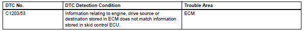
Description
The circuit is used to send trc and vsc control information from the skid control ecu to the ecm, and engine control information from the ecm to the skid control ecu.
Inspection procedure
Hint:
Check that the part numbers of the installed ecm and skid control ecu are correct before performing the following procedure.
- Reconfirm dtc
- Clear the dtc (see page bc-47).
- Start the engine.
- Check if the same dtc is output (see page bc-47).
Result 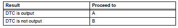


Replace ecm
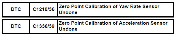
Zero point calibration
Description
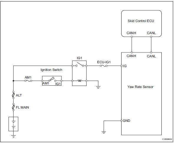
The abs and traction actuator (skid control ecu) receives signals from the yaw rate and deceleration sensor via the can communication system. The yaw rate sensor has a built-in deceleration sensor and detects the vehicle's condition using 2 circuits (gl1, gl2). If there are problems in the bus lines between the yaw rate and deceleration sensor and the can communication system, dtcs u0123/62 (yaw rate sensor communication trouble) and u0124/95 (deceleration sensor communication trouble) are output.
The dtcs are also output when the calibration has not been completed.
Wiring diagram
Inspection procedure
Notice:
When replacing the abs and traction actuator, perform the zero point calibration (see page bc- 24).
Hint
When dtc u0123/62, u0124/95 or u0126/63 is output together with dtc c1210/36 or c1336/39, inspect and repair trouble areas indicated by dtc u0123/62, u0124/95 or u0126/63 first.
- Check yaw rate sensor installation
- Check that the yaw rate sensor has been installed properly (see page bc-211).
Ok: the sensor is tightened to the specified torque.
The sensor is not tilted.

- Perform zero point calibration of yaw rate sensor
- Perform zero point calibration of the yaw rate and deceleration sensor (see page bc-24).

- Reconfirm dtc
- Clear the dtc(s) (see page bc-47).
- Start the engine.
- Drive the vehicle and turn the steering wheel to the right and left at a speed of 45 km/h (28 mph) or more.
- Check if the same dtc(s) is recorded (see page bc- 47).
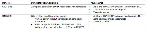
Result 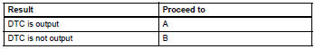
Hint:
- The dtc(s) is set if the zero point calibration has not been completed successfully.
- End the procedure when the same dtc(s) is not set after completion of the zero point calibration.

Replace abs and traction actuator assembly
 Engine control system malfunction
Description
If a malfunction in the engine control system is detected, the operations of
vsc and trc are prohibited
by the fail-safe function. When the signals from the engine are input normal ...
 Abs control system malfunction
Description
This dtc is output when the vsc system detects a malfunction in the abs
system.
Inspection procedure
Check dtc for abs system
Clear the dtc (see page bc-47).
Turn t ...
Other materials:
Front console illumination
On-vehicle inspection
Inspect front console illumination
Connect the battery's positive (+) lead to terminal 1
and the negative (-) lead to terminal 2, then check
that the light comes on.
Ok:
light comes on.
If the result is not as specified, replace the front
console illumin ...
Pressure sensor circuit
Description
This dtc is output when the refrigerant pressure is either extremely low
(0.19 Mpa [2.0 Kgf/cm2, 28 psi]
or less) or extremely high (3.14 Mpa [32.0 Kgf/cm2, 455 psi] or more). The air
conditioning pressure
sensor, which is installed on the pipe of the high pressure side, detec ...
Open in occupant classification ecu battery positive line
Description
Dtc b1794 is set when a malfunction is detected in the occupant
classification ecu battery positive line.
Wiring diagram
Inspection procedure
Check for dtc
Turn the ignition switch on.
Clear the dtcs (see page rs-249).
Hint:
First clear dtcs stored in the ...
