Toyota RAV4 (XA40) 2013-2018 Service Manual: Disassembly (2006/01- )
- Remove front axle inboard joint boot no. 2 Clamp
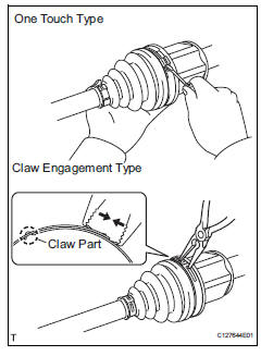
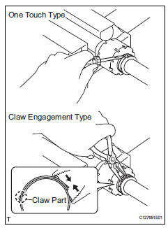
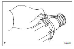
- One touch type: using a screwdriver, remove the inboard joint boot clamp, as shown in the illustration.
- Claw engagement type: using needle-nose pliers, remove the inboard joint boot clamp, as shown in the illustration.
- Remove front axle inboard joint boot clamp
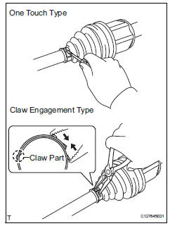
- One touch type: using a screwdriver, remove the inboard joint boot clamp, as shown in the illustration.
- Claw engagement type: using needle-nose pliers, remove the inboard joint boot clamp, as shown in the illustration.
- Remove front axle inboard joint boot
- Remove the boot from the inboard joint.
- Remove front drive inboard joint assembly lh
- Remove any old grease from the inboard joint.
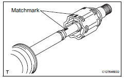
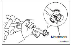
- Put matchmarks on the inboard joint and outboard joint shaft.
Notice:
Do not punch the marks.
- Remove the inboard joint from the outboard joint shaft.
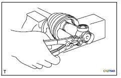
- Using a snap ring expander, remove the shaft snap ring.
- Put matchmarks on the outboard joint shaft and tripod joint.
Notice:
Do not punch the marks.
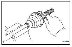
- Using a brass bar and hammer, tap out the tripod joint from the outboard joint shaft.
Notice:
Do not tap the rollers.
- Remove the inboard joint boot.
- Remove front drive inboard joint assembly rh
Hint:
Use the same procedures described for the lh side.
- Remove front drive shaft damper clamp lh
- One touch type: using a screwdriver, remove the drive shaft damper clamp, as shown in the illustration.
- Claw engagement type: using needle-nose pliers, remove the drive shaft damper clamp, as shown in the illustration.
- Remove front drive shaft damper lh
- Remove the front drive shaft damper from the outboard joint shaft.
- Remove front axle outboard joint boot no. 2 Clamp
- Using a screwdriver, remove the outboard joint boot clamp, as shown in the illustration.
- Remove front axle outboard joint boot clamp
- Using a screwdriver, remove the outboard joint boot clamp, as shown in the illustration.
- Remove front axle outboard joint boot
- Remove the outboard joint boot from the outboard joint shaft.
- Remove any old grease from the outboard joint.
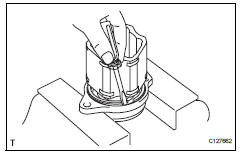
- Remove front drive shaft hole snap ring lh
- Using a screwdriver, remove the hole snap ring.
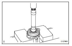
- Remove front drive shaft dust cover lh
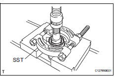
- Using sst and a press, press out the shaft dust cover.
Sst 09950-00020
Notice:
Be careful not to drop the inboard joint.
- Remove front drive shaft dust cover rh
Hint:
Use the same procedures described for the lh side.
- Remove drive shaft bearing case (for rh)
- Using a screwdriver, remove the bearing case snap ring.
- Using a press, press out the drive shaft bearing case.
Hint:
Be careful not to drop the inboard joint.
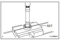
- Remove front drive shaft dust cover (for rh)
- Using sst and a press, press out the drive shaft dust cover.
Sst 09950-00020
Notice:
Be careful not to drop the inboard joint.
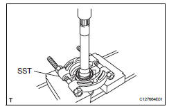
- Remove front drive shaft bearing
- Using a snap ring expander, remove the snap ring.
- Using sst and a press, press out the drive shaft bearing.
Sst 09527-10011
- Remove the bearing case snap ring.
 Disassembly (2005/11-2006/01)
Remove front axle inboard joint boot no. 2 Clamp lh
One touch type:
Using a screwdriver, remove the inboard joint
boot clamp, as shown in the illustration.
Claw engagement t ...
 Reassembly (2005/11-2006/01)
Install drive shaft bearing case subassembly
Using sst and a press, press in the drive shaft
bearing case to the inboard joint rh.
Sst 09527-10011, 09710-04081
Notice:
The bearing ...
Other materials:
Steering wheel
Adjustment procedure
The steering wheel can be adjusted to a comfortable position.
Hold the steering wheel and
press the lever down.
Adjust to the ideal position by
moving the steering wheel horizontally
and vertically.
After adjustment, pull the lever up
to secure the steering ...
Slip indicator light does not come on
Description
Refer to the description of "slip indicator light remains on" (see page
bc-152).
Wiring diagram
Refer to the slip indicator light circuit (see page bc-152).
Inspection procedure
Notice:
When replacing the abs and traction actuator, perform the zero point
calibration ( ...
Reassembly
V
Attach the 7 outside moulding retainers to install the
extension.
Install front bumper extension rh (for wide
body)
Hint:
Use the same procedures described for the lh side.
Install front bumper hole cover lh (w/o fog
light)
Install the bumper hole cover with ...
