Toyota RAV4 (XA40) 2013-2018 Service Manual: Compressor lock sensor circuit
![]()
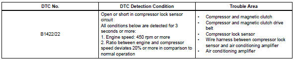
Description
This sensor sends 1 pulse per engine revolution to the air conditioning amplifier. If the ratio of the compressor speed divided by the engine speed is smaller than a predetermined value, the air conditioning amplifier turns the compressor off, and the indicator blinks at approximately 1 second intervals.
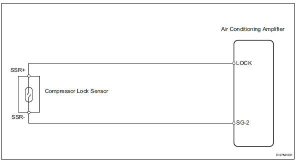
Wiring diagram
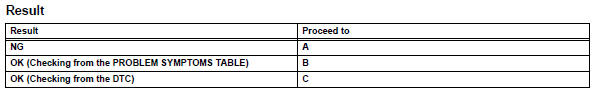
Inspection procedure
- Check air conditioning amplifier (lock signal)
- Remove the air conditioning amplifier with its connectors still connected.
- Check the waveform of the amplifier connector.
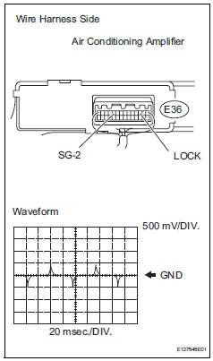
Ok:
waveform is as shown in the illustration.


- Inspect compressor lock sensor
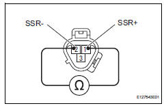
- Disconnect the b47 compressor lock sensor connector.
- Measure the resistance of the sensor.
Standard resistance 


- Check wire harness (compressor lock sensor - air conditioning amplifier)
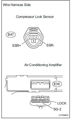
- Disconnect the b47 compressor lock sensor connector.
- Disconnect the e36 amplifier connector.
- Measure the resistance of the wire harness side connectors.
Standard resistance 


Replace air conditioning amplifier
 Evaporator temperature sensor circuit
Description
The no. 1 Cooler thermistor (evaporator temperature sensor) is installed on
the evaporator in the air
conditioning unit to detect the temperature of the cooled air that has passed ...
 Pressure sensor circuit
Description
This dtc is output when the refrigerant pressure is either extremely low
(0.19 Mpa [2.0 Kgf/cm2, 28 psi]
or less) or extremely high (3.14 Mpa [32.0 Kgf/cm2, 455 psi] or more). The ...
Other materials:
Driver side seat belt buckle switch circuit malfunction
Description
The driver side seat belt buckle switch circuit consists of the center airbag
sensor and the front seat inner
belt lh.
Dtc b1655/37 is recorded when a malfunction is detected in the driver side seat
belt buckle switch circuit.
Wiring diagram
Inspection procedure
...
Room temperature sensor (for automatic ai conditioning system)
Components
Removal
Remove lower instrument panel
Remove the lower instrument panel (see page ip-
16).
Remove room temperature sensor
Disconnect the duct.
Disconnect the connector.
Detach the claws and remove the sensor.
Inspection
Inspect room temperature ...
Steering angle sensor
Components
Removal
Precaution
Caution:
Be sure to read the "precaution" thoroughly
before servicing (see page rs-1).
Disconnect cable from negative battery
terminal
Caution:
Wait at least 90 seconds after disconnecting the
cable from the negative (-) battery termin ...
