Toyota RAV4 (XA40) 2013-2018 Service Manual: Abs warning light remains on
Description
If any of the following conditions are detected, the abs warning light remains on:
- The ecu connectors are disconnected from the skid control ecu.
- There is a malfunction in the skid control ecu internal circuit.
- There is an open or short in the wire harness between the combination meter and the skid control ecu.
Hint:
The intelligent tester may not be used when there is a malfunction in the skid control ecu.
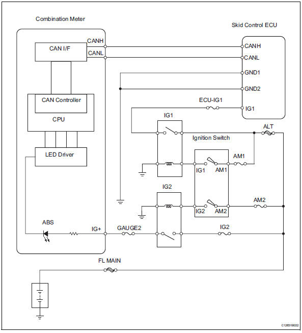
Wiring diagram
Inspection procedure
- Check can communication system
- Check if the can communication system dtc is output (see page ca-34).
Result 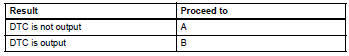

- Inspect skid control ecu connector
- Check if the skid control ecu connector is properly installed.
Ok: the skid control ecu connector is properly installed.

- Check wire harness (skid control ecu - battery and body ground)
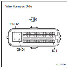
- Disconnect the a19 ecu connector.
- Measure the resistance of the wire harness side connector.
Standard resistance 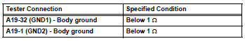
- Measure the voltage of the wire harness side connector.
Standard voltage 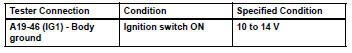

- Perform active test by intelligent tester (abs warning light)
- Select the active test, generate a control command, and then check that the abs warning light operates.

Ok: the abs warning light is turned on or off.
Hint:
When the abs warning light remains illuminated, opens in the wire harness of the combination meters or abnormalities in the meter circuit should be considered.

Replace abs and traction actuator assembly
 Control module communication bus off
Description
Inspection procedure
The skid control ecu inputs the signals from the ecm, steering angle sensor,
and yaw rate and
acceleration sensor via can communication system.
Ch ...
 Abs warning light does not come on
Wiring diagram
Refer to the abs warning light circuit (see page bc-135).
Inspection procedure
Check can communication system
Check if the can communication system dtc is output
(see page ...
Other materials:
Air fuel ratio sensor
Components
On-vehicle inspection
Check air fuel ratio compensation system
Connect the intelligent tester to the dlc3.
Turn the ignition switch on.
Select the following menu items: data list / a/fs b1
s1 and o2s b1 s2.
Warm up the a/f sensor with the engine speed at
2,500 ...
Problem symptoms table (2005/11-2006/01)
Hint:
Use the table below to help determine the cause of the
problem symptom. The potential causes of the symptoms
are listed in order of probability in the "suspected area"
column of the table. Check each symptom by checking the
suspected areas in the order they are listed. Re ...
Source voltage drop
Description
The srs is equipped with a voltage-increase circuit (dc-dc converter) in the
center airbag sensor in
case the source voltage drops.
When the source voltage drops, the voltage-increase circuit (dc-dc converter)
functions to increase the
voltage of the srs to a normal working lev ...
